BILGE PUMP
FWD
WATER
PUMP
ENGINE ROOM
FAN
NAVIGATION
LIGHTS
ANCHOR
LIGHT
SALOON LTS
PORT
SALOON LTS
STBD
GALLEY
LIGHTS
COCKPIT
LIGHT
STEP
LIGHTS
HEAD
LIGHT
CABIN
LIGHTS
NIGHT
LIGHTS
CABIN CTSY
LIGHTS
COCKPIT CTSY
LIGHTS
1 2 3
4 5
6
7
8 9 10 11 12 13 14 15 16
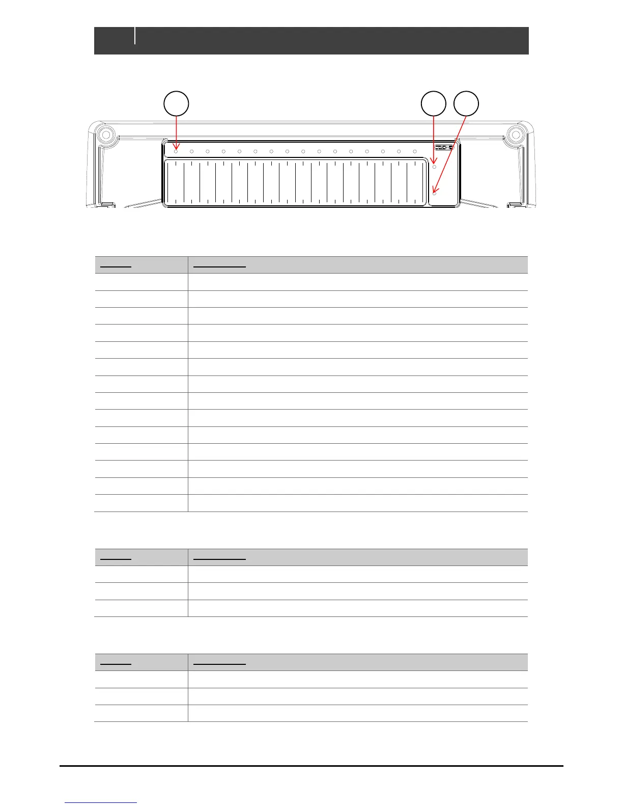
Green - Power
Red Flash - Traffic
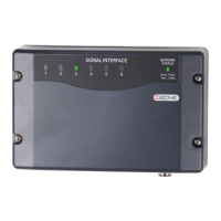
NETWORK
STATUS
Green - Available
Red - Low Volts
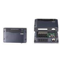
COI
POWER
Manual Fuse Bypass
Warning! Inserting
fuse creates ignition
hazard, ensure area is
free of explosive
gases
BYPASS
NORMAL
FUSE
NMEA IN-D
OUT-L (5-16) IN-A (1-8)
BILGE PUMP
AFT
Analogue Inputs (IN-A)
1 _________________________
2 _________________________
3 _________________________
4 _________________________
5 _________________________
6 _________________________
7 _________________________
8 _________________________
Digital Switch Inputs (IN-D)
1 _____________________
2 _____________________
3 _____________________
4 _____________________
5 _____________________
6 _____________________
1
DIP
COI
2 3
4 5
6
7
8
__________________
Channel LED Status Codes
GRN solid on = Channel on
1 x RED = Module not configured
2 x RED = Configuration conflict
3 x RED = Dip switch conflict
4 x RED = Memory failure
5 x RED = No modules detected
6 x RED = Low run current
7 x RED = Over current
8 x RED = Short circuit
9 x RED = Missing commander
10 x RED = Over temperature
11 x RED = Reverse current
12 x RED = Current calibration
OUT-H (1-4)