18
8
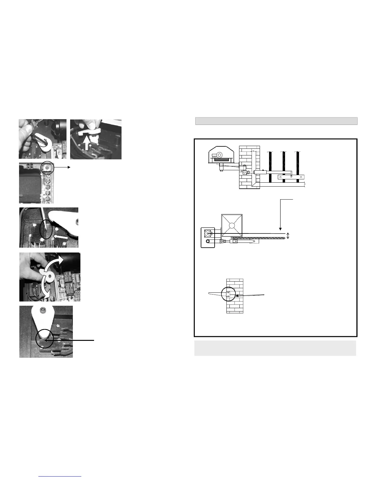
When gate reaches the required open position, press
the limit switch.
This is made easier using a small flat screwdriver.
The motor will stop.
The limit switch can be released when the operators
have stopped running.
Press the test button on the PC Board. The gates will now
start opening.
Lift and turn the rotor until it presses on the limit
switch.
Tighten the rotor . Do not over tighten.
The limit switches are now set and the gates can now
be operated.
Rotor on open limit switch.
Rotor must be in this position when the
gates are fully open.
4
Loosen the limit rotor . The
rotor is a black plastic cam
shaped rotor. The rotor
can be removed com-
pletely to assist with the
set-up
5
6
7
15
WALL MOUNT : OUTWARD SWING
All OUTWARD swing installations require SHORT crank arms and LONG conrods.
When outward swing gates are setup the operators will protrude into the driveway by 155mm
on each side of the driveway. Any attempt to mount the operators in any other manner will
cause operational problems with the gates.
GATE IN OPEN POSITION
With the outward swing Wall
Mount method, the Wall Mount
Bracket must be modified and a
steel plate (not supplied) must be
bolted or welded to the bracket so
that it can be fastened on the
inside of the gate post.
This measurement is critical!
With the gate in the open position, the
distance between the centre line of the
Wall Mount Bracket and the inner face
of the gate must be 70mm.
70mm