16
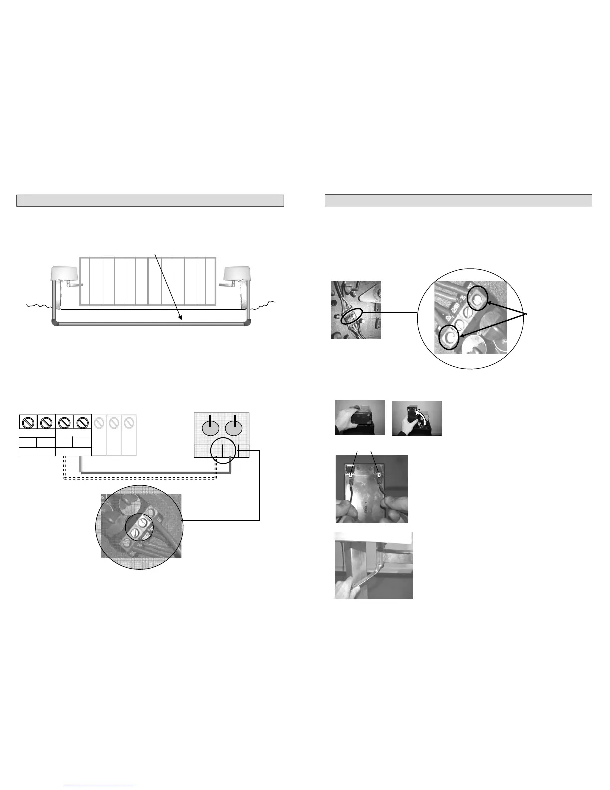
WIRING THE SLAVE OPERATOR
Ensure that the cable is connected in the correct order. The cable must be connected from the PC Board
output labeled MOTOR 2, to the limit switch diodes on the slave operator. The cable that is connected to the
“A “output must be connected to the “A” input on the limit switch diodes. And the “B” output must be con-
nected to the “B” input.
See diagram below.
Conduit must be run between the two operators with a 2.5mm cable from the master motor to the
slave motor. This cable is connected from the main PC Board on the master to the slave motor limit
switch diodes. Using thinner cable will result in a voltage drop across the driveway resulting in the
gates operating at different speeds (i.e the slave will move slower than the master).
A B
Main PC Board on the operator
Limit switch diodes on the slave operator
MOTOR 1
MOTOR 2
A B
17
SETTING THE LIMITS
There are two limit switches and a limit rotor in each operator. The function of these is to stop the
operators turning when the limit switch is struck by the rotor which is attached to the main shaft.
Before setting up the limit switches you have to establish the closing direction of the operators. The
operators should automatically drive to the closed position when first powered up but as each site is
unique it may not. Apply power to the motor and take note of the direction that the shaft turns.
NOTE: If it is determined that the operators are turning the correct way, continue to set up the
limit switches as shown below.
If the operators are turning the incorrect way you must reverse the motor wires. Follow the
instruction below before continuing to set up the limit switches.
In order to reverse
the motor direc-
tion, reverse these
two wires.
1
2
DO NOT REVERSE
BATTERY CABLES
Remove the power. Reverse the motor wires at the limit diodes as shown above.
The operators should be running in the correct direction i.e. when the CLOSE LED is on the gates
must be closed and when the OPEN LED is on the gates must be open. Now proceed to set up the
limit switches.
Stand the battery up in a vertical posi-
tion to allow for access to the limit rotor.
Apply the battery power.
The operators will automatically turn until the closed limit
is struck.
Before tightening the crank arms ensure that the gates are
set up correctly using the diagrams on pages 11 –15.
The gates must now be placed in the closed position and
the crank arms can now be tightened. (23mm spanner.) .
3
 Loading...