26
Used to stop the gate closing even if the vehicle is past the first set of beams but it may still be in the
path of the closing gate. One set mounted on the gate posts and the other set mounted clear of the
gate when the gate is in the open position.
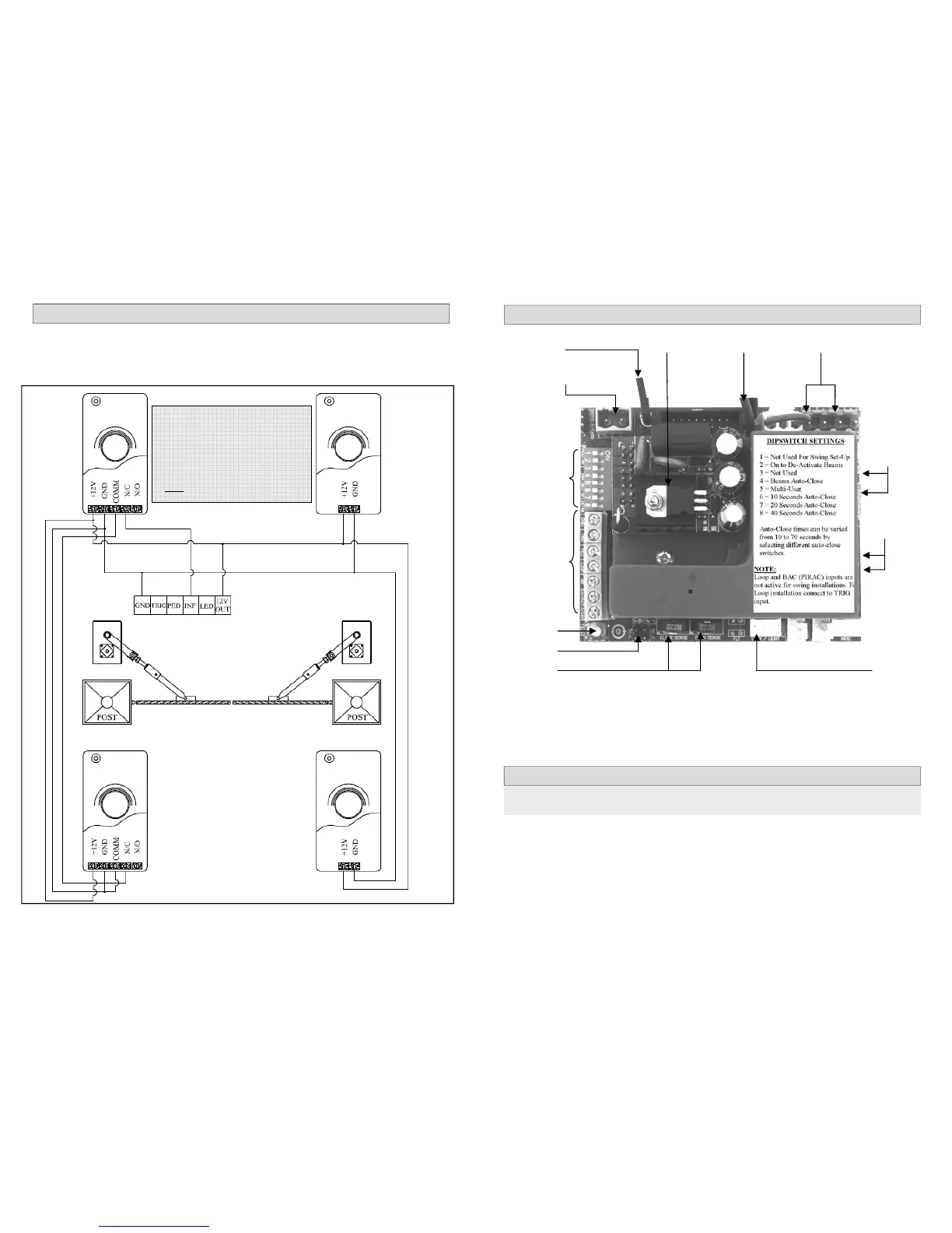
WIRING TWO SETS OF INFRARED SAFETY BEAMS (DuraOptics)
Covers must be in place when beams
are active. Ensure that the correct
cover is placed onto each beam after
setup otherwise failure to do so may
result in faulty operation of the
beams.
Ensure that number 2 dipswitch is set
“OFF
” after connecting the beams.
Main PC Board
7
MAIN PC BOARD LAYOUT
NOTE: The PC Board is a delicate piece of electronic equipment. Take care when connecting or dis-
connecting any wiring from the board. Ensure that ALL power is removed before any wiring connec-
tions are done on the board, failure to do so may damage the board. Do not reverse the battery
polarity as this will cause serious damage to the PC board. Do not spray any type of insecticide or
lubricant spray onto the board as this may cause damage. Never touch the board with any metal ob-
jects (screwdrivers etc). Do not attempt to repair the board in any way, take the board to a recognized
D.A.C.E. dealer for any repairs needed.
ELECTRICAL WIRING
If the intention is to run 230V (high voltage ) to the motor, it is strongly recommended that the local
E.C.A. (Electrical Contractors Association) is contacted in the area before any wiring is done to obtain
the local requirements regarding electrical wiring regulations. Running 230V must be done by a regis-
tered electrician, failure to do this may lead to legal action in the case of electrical shock.
Furthermore it is illegal to run 230V and communication (intercom) cables in the same conduit.
D.A.C.E. recommends that the transformer is removed from the motor and plugged into an outlet
socket inside the house. This means that the power running to the operators is 16 VAC and does not
require an electrician to install it. All wiring must be sealed in conduit and buried underground. (DO
NOT connect to pool pump that uses a timer or to pillar lights with a day night sensor. This will result in
a flat battery).
Auxiliary
connectors
Open / close
LED
Test button
Dipswitches
Motor wire
connectors
10 amp
motor fuses
16 VAC connector
from transformer
Earth wire
Battery wires
(red & black)
Light / lock
connector
Pluggable
Charger
Remote learn
jumper
Current
sensing pots
WARNING: electrical shock may occur during installation of this equipment,
please use caution at all times.
 Loading...