24
CONNECTING AN EXTERNAL RECEIVER
When connecting any auxiliary equipment to the PC Board ensure that all power is removed
from the PC Board.
PEDESTRIAN OPERATION: A separate receiver, keyswitch or keypad must be connected to operate
the gate in the pedestrian mode. The connection is done in the same manner as the diagram above
with the exception of the TRIG connection. Instead of TRIG to N/O it must be PED on the main PC
Board to N/O.
In pedestrian mode the gate will open partially and then close automatically after 6 seconds.
To program remotes to the receiver:
1. Press and hold the button on the remote.
2. Place the jumper over the two TX LEARN pins for 1 second.
3. Remove the jumper.
4. Release the button on the remote.
Repeat the above steps for each remote to be programmed.
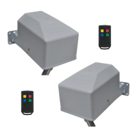
A DuraTronic external receiver can be connected to the PC Board. This will be necessary if there are
more than 15 remotes to be used or if the range of the on-board receiver is not sufficient.
The DuraTronic external receiver can hold 128 remotes. The DuraTronic receiver should be mounted
outside the operator housing for increased range.
CONNECTOR BLOCKS ON MAIN PC BOARD
GND PED
LED/
STAT
INF
LOOP 12/
24V
TRIG
12/
24
COM N/O
N/C
NEG
CONNECTOR BLOCKS ON
EXTERNAL RECEIVER
9
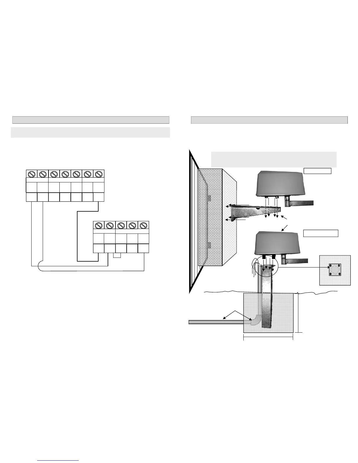
MOUNTING THE OPERATORS
The operators can be mounted either as a Wall Mount and Pedestal Mount.
The diagrams below show the two types of mounting.
When a Wall Mount is used it is recommended that normal coach screws and plugs are used to se-
cure the wall mount to the wall.
For a Pedestal Mount a 400mm square hole must be dug (per pedestal) and then filled with concrete
and the pedestal placed in the centre. Do not mount the operators until the concrete is fully cured.
WALL MOUNT
Secure the operators using
the four nuts supplied
Conduit for electrical cables.
Ensure this is done before
the concrete is paced into
the hole
PEDESTAL MOUNT
400mm
400mm
Concrete
Ensure that the operator
is at right angels to the
gate
TOP VIEW
Concrete
NOTE: the diagrams below show mounting position for Inward Swing. For
Outward Swing the operators must be turned 90° on the mountings.
(see pg 12 or 15).