D-Link NetDefend Firewall 3
ENGLISH
Item Feature Description
A LCD Panel Used to display status and operation
messages.
B Keypad These keys are used in conjunction with
the messages on the LCD Panel.
C LEDs Power LED (top): Indicates that the
NetDefend UTM rewall is powered on.
System LED (bottom): Indicates the
system status of the NetDefend UTM
rewall
D Console Port Used to access the NetDefendOS
Command Line Interface (CLI) via
RS232 Cable.
E USB Ports (2) Reserved for future use.
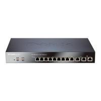
F 10/100/1000Mbps
Ethernet Ports*
The assigned numbers for the ports are
5 to 10 (from left to right).
G 10/100/1000Mbps
Ethernet Ports*
(DFL-2560)
The assigned numbers for the ports are
1 to 4 (from left to right).
1000Mbps
SFP Port*
(DFL-2560G)
Table 3. DFL-2560/DFL-2560G Front Panel Descriptions
* Congurable Gigabit Ethernet ports with autosensing
duplex and auto MDI/MDIX. When conguring one of the
ports, reference the interface name that corresponds to
the location of the port. For the default interface name
bindings for each Ethernet port, see Table 4 “Default
Interface Assignment”.
Device Status LEDs and Ethernet Port LEDs
The device LEDs show information about current
device status. When the device is powered up,
the POWER LED changes from off to solid
green and the SYSTEM LED changes from off
to solid green. Startup takes approximately one
minute to complete. The Ethernet LEDs show
the status of each Ethernet port. Table 5 lists
the name, color, status, and description of each
device LED.
Note: If you would like to turn the device off and
on again, we recommend waiting a few seconds
between shutting it down and powering it back on.
Name Color Status - Description
Power Green Light Off - Device is powered
off.
Solid Green - Device is
powered on.
System Green/
Orange
Light Off - Device is powered
off or is starting up.
Solid Green - System is normal
operation.
Solid Orange - System failure
or license lockdown.
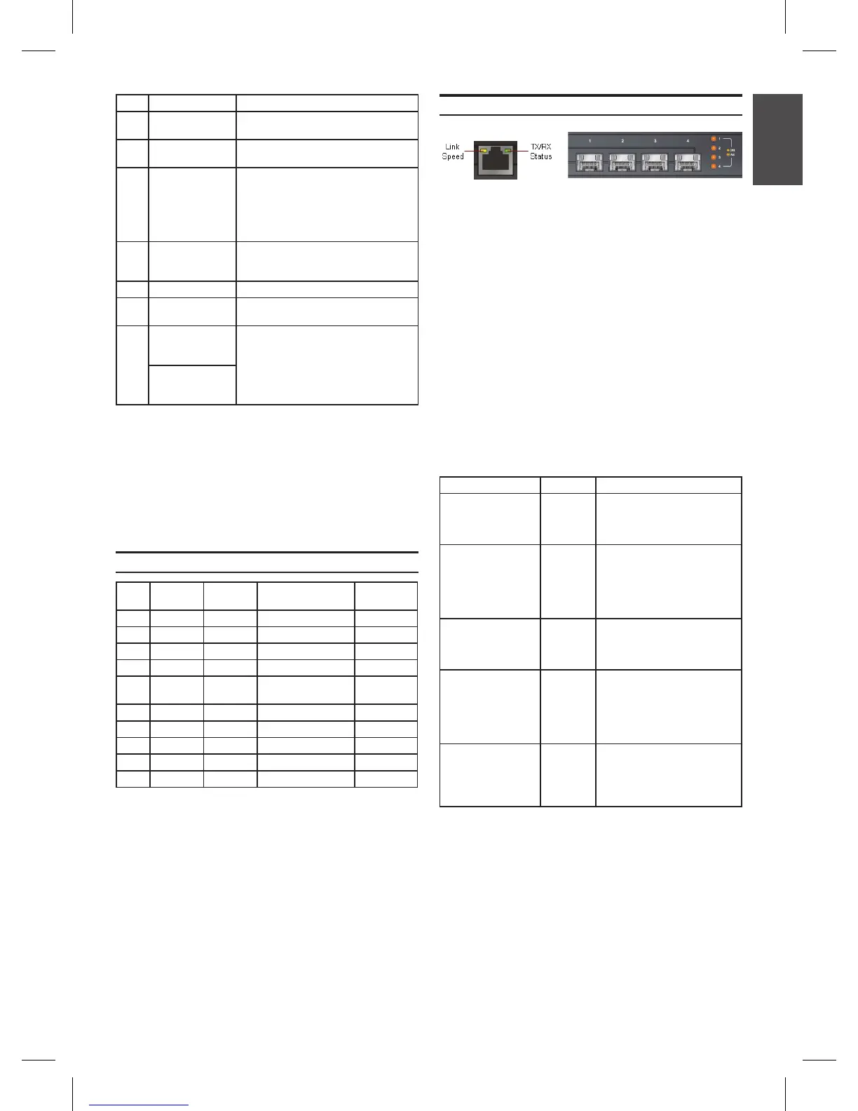
TX/RX Status Green Light Off - No Link.
Solid Green - Link present.
Blinking Green - Port is
sending or receiving data.
LINK Speed Green/
Orange
Light Off - Port is operating at
10Mbps.
Solid Green - Port is operating
at 100Mbps.
Solid Orange - Port is
operating at 1000Mbps.
Link and TX/RX for
SFP port
(DFL-2560G only)
Orange Light Off - No Link.
Solid Orange - Link Present
and operating at 1000Mbps.
Blinking Orange - Port is
sending or receiving data.
Figure 3. Ethernet
RJ-45 Port LEDs
Figure 4. Ethernet
SFP Port LEDs
(DFL-2560G only)
Table 5. Device Status LED Descriptions
Port
Interface
Name
Interface
Type IP Address
Web-Based
Mgmt
1 DMZ1 Static IP 172.17.100.254/24 Disabled
2 DMZ2 Static IP 172.17.110.254/24 Disabled
3 DMZ3 Static IP 172.17.120.254/24 Disabled
4 DMZ4 Static IP 172.17.130.254/24 Disabled
5 WAN1 DHCP
Client
N/A Disabled
6 WAN2 Static IP 192.168.120.254/24 Disabled
7 LAN1 Static IP 192.168.10.1/24 Enabled
8 LAN2 Static IP 192.168.20.1/24 Disabled
9 LAN3 Static IP 192.168.30.1/24 Disabled
10 LAN4 Static IP 192.168.40.1/24 Disabled
DFL-2560/DFL-2560G Default Interface Settings
Table 4. Default Interface Assignment
Note: D-Link NetDefend Firewalls only allow
Web GUI access from the LAN1 port by default
for security reasons. That means the Web GUI
access is only allowed on port No. 7 of front
plate by default for DFL-2560/DFL-2560G.
 Loading...