Do you have a question about the D-Link DGS-1210-28P and is the answer not in the manual?
Defines terms like "Switch" and "switch" for clarity in the manual.
States copyright information and trademarks used within the document.
Details the flexible port configurations of the DGS-1210 series switches.
Explains D-Link's green initiatives for energy saving on the switches.
Lists Layer 2 features like IGMP snooping, port mirroring, and Spanning Tree.
Describes VLAN, QoS, and Auto Surveillance VLAN for network management.
Highlights security features like Safeguard Engine and 802.1X port-based authentication.
Discusses the Web-based management interface and Telnet access for switch management.
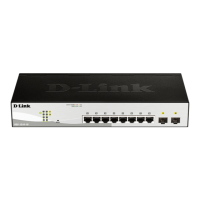
Describes the components and LEDs on the front panel of the DGS-1210-10 switch.
Shows the rear panel of the DGS-1210-10 and identifies the power connector.
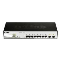
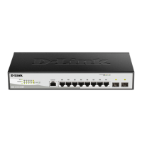
Details the front panel components and LEDs, including PoE Max, for the DGS-1210-10P.
Shows the rear panel of the DGS-1210-10P and identifies the power connector.
Describes the front panel components and LEDs, including PoE Max, for the DGS-1210-10MP.
Shows the rear panel of the DGS-1210-10MP and identifies the power connector.
Details the front panel components and LEDs for the DGS-1210-20 switch.
Shows the rear panel of the DGS-1210-20 and identifies the power connector.
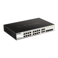
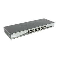
Describes the front panel components and LEDs for the DGS-1210-26 switch.
Shows the rear panel of the DGS-1210-26 and identifies the power connector.
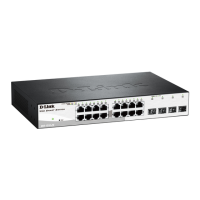
Details the front panel components and LEDs for the DGS-1210-28 switch.
Shows the rear panel of the DGS-1210-28 and identifies the power connector.
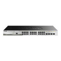
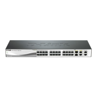
Describes the front panel components and LEDs, including PoE Max, for the DGS-1210-28P.
Shows the rear panel of the DGS-1210-28P and identifies the power connector.
Details the front panel components and LEDs, including PoE Max, for the DGS-1210-28MP.
Shows the rear panel of the DGS-1210-28MP and identifies the power connector.
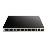
Describes the front panel components and LEDs for the DGS-1210-52 switch.
Shows the rear panel of the DGS-1210-52 and identifies the power connector.
Details the front panel components and LEDs, including PoE Max, for the DGS-1210-52MP.
Shows the rear panel of the DGS-1210-52MP and identifies the power connector.
Explains the 'Power' and 'Fan Error' LEDs for device status indication.
Details the 'PoE Max' LED status for PoE power budget indication.
Describes the Link/Act and PoE LED states for copper ports.
Describes the Link/Act LED states for SFP ports.
Essential safety precautions for installing the switch to prevent injury or damage.
Guides users through unpacking, installing the switch, and connecting power safely.
Details the steps for connecting the switch to a protective ground for safety.
Outlines the available management options for the Smart Managed Switch.
Explains accessing the switch via web browser, including login and initial setup.
Introduces the Smart Wizard for guiding users through essential switch settings.
Describes how to access the main web-based management interface after exiting the Smart Wizard.
Explains the Smart Wizard utility for initial switch configuration.
Guides through selecting the web interface mode (Standard or Surveillance) in the Smart Wizard.
Details configuring IP address assignment methods and network details.
Explains how to set a new password for secure access to the switch.
Guides on enabling or disabling the SNMP function for network management.
Describes the main Web-based Management screen layout and areas.
Provides access to utility functions via the Tool Bar.
Allows configuration of IP address and basic system information.
Explains how to set or change the switch's password for security.
Allows monitoring and adjusting port settings like speed, MDI/MDIX, and flow control.
Explains enabling DHCP Auto Configuration for automatic file retrieval on boot.
Allows configuration of global DHCP Relay settings, including hop limits.
Allows setting up DHCP relay servers by IP address.
Explains configuration for DHCP Local Relay status and VLAN settings.
Allows configuration of DHCPv6 Relay settings.
Covers enabling system logs and configuring save modes for log entries.
Details settings for configuring a remote Syslog server for system logs.
Allows configuration of time profiles for scheduling various switch functions.
Explains power saving features like LED shut-off and port shut-off based on schedules.
Describes enabling IEEE 802.3az EEE for energy saving on network links.
Allows disabling or configuring the D-Link Discovery Protocol (DDP).
Displays information about the switch's firmware.
Explains configuring 802.1Q VLANs for network segmentation and organization.
Allows configuration of the PVID for each port.
Enables and configures global settings for Voice VLAN to prioritize voice traffic.
Allows automatic placement of voice traffic into assigned VLANs based on OUI.
Displays information about devices configured for Voice VLAN.
Allows configuration of settings for Auto Surveillance VLAN.
Describes configuring user-defined MAC settings and detecting surveillance devices.
Displays information about connected ONVIF IP cameras.
Displays information about connected ONVIF NVRs.
Explains how to enable support for Jumbo Frames for larger packet sizes.
Describes configuring Port Mirroring to monitor network traffic by copying packets.
Details the Loopback Detection function to detect and shut down network loops.
Allows turning off MAC address learning and configuring static MAC entries.
Displays the MAC addresses learned by the switch for each port.
Configures global settings for Spanning Tree Protocol (STP), RSTP, and MSTP.
Configures STP parameters on a per-port basis.
Configures Multiple Spanning Tree Instances (MSTI) for advanced spanning tree setups.
Displays and allows modification of MSTP instance settings and priorities.
Allows updating port configurations for an MSTI ID and viewing MSTP port information.
Enables combining multiple ports to increase bandwidth using Static or LACP link aggregation.
Configures LACP port settings for active and passive roles in trunking groups.
Explains IGMP Snooping for intelligent multicast forwarding and reducing network clutter.
Describes MLD Snooping for IPv6 multicast traffic management.
Implements static multicast forwarding table entries.
Selects filtering modes for IGMP groups per VLAN.
Configures SNTP settings for synchronizing the switch's clock with an external time source.
Configures time zones and Daylight Saving Time settings for SNTP.
Configures global settings for Link Layer Discovery Protocol (LLDP) to advertise device information.
Enhances LLDP with Media Endpoint Discovery features for IP phones and APs.
Displays and configures LLDP port information and parameters.
Configures LLDP port settings using 802.1 Extension TLVs.
Configures LLDP port settings using 802.3 Extension TLVs.
Sets management addresses included in LLDP information transmission.
Displays detailed management address information for LLDP entries.
Displays LLDP local port information.
Displays an overview of all LLDP traffic statistics.
Allows configuration of IP interfaces, including IPv4 and IPv6 settings.
Enables and configures static IPv4 routes for network traffic management.
Enables and configures static IPv6 routes for network traffic management.
Displays and manages ARP entries on the switch, including static entries.
Defines static ARP entries to map IP addresses to MAC addresses.
Defines bandwidth settings for specified ports' transmitting and receiving data rates.
Configures Quality of Service priority levels for traffic based on 802.1p, DSCP, or ToS.
Manages trusted hosts by defining IP addresses allowed to access the switch.
Prevents unauthorized computers from accessing the network by securing MAC addresses to ports.
Limits traffic flow from ports to groups of ports, offering finer control than VLANs.
Protects the switch CPU from packet flooding and malicious attacks.
Controls the rate of broadcast, multicast, and unknown unicast packets to prevent storms.
Discards ARP spoofing attacks by checking gratuitous ARP packets and filtering illegal entries.
Restricts illegal DHCP servers by discarding service from distrusted ports.
Provides secure communication via SSL/TLS for Web Management, enabling encryption and authentication.
Configures SSL ciphersuites for encryption and authentication strength.
Enables or disables prevention for various Denial of Service (DoS) attacks.
Configures SSH server settings for secure remote login and network services.
Configures SSH authentication modes and encryption algorithms.
Configures user authentication parameters for SSH access to the switch.
Restricts client access by enabling IP-MAC-port binding and packet inspection.
Allows manual or scanned IP-MAC-Port Binding entries.
Displays IP-MAC-Port Binding entries that are allowed access to the switch.
Lists unauthorized accesses and devices forbidden due to unmatched IP-MAC-Port information.
Facilitates centralized user administration and protection against sniffing via RADIUS server.
Configures global settings for 802.1X port-based network access control.
Sets 802.1X port settings for Radius Server and authentication details.
Allows setting up local users for 802.1X authentication on the switch.
Guides through the creation of access profiles and ACL rules for packet filtering.
Displays and configures global PoE settings, including system power budget.
Lists and configures PoE port specifications and settings.
Configures global SNMP settings, including trap settings and enabled state.
Manages SNMP users, specifying version, authentication, and privacy protocols.
Maintains SNMP group tables for controlling MIB access policy and security.
Maintains SNMP views to define MIB objects accessible by remote managers.
Manages SNMP community strings for access control to the switch's SNMP agent.
Configures SNMP trap recipients by specifying host IP addresses and SNMP versions.
Enables/disables Remote Monitoring (RMON) status and alarm traps.
Displays and configures RMON Ethernet Statistics.
Contains information about samples of data taken from ports for history control.
Configures network alarms for detecting network problems or events.
Displays packet count status for each port.
Diagnoses copper cable quality and detects cable errors.
Provides information about system logs, including device boot-up and user logins.
Describes entering the Web User Interface for surveillance mode.
Loads Surveillance Topology and Device Information tabs upon login.
Displays a diagram of the surveillance topology and connected devices.
Provides detailed information about the switch, PoE utilization, and bandwidth usage.
Displays the port status, including throughput, PoE, and connected devices.
Shows information on each connected IP camera, including IP address and port.
Displays information on connected NVRs, including camera details.
Shows PoE usage information for each port, including budget and power consumption.
Allows scheduling power delivery to PoE ports to save energy or enhance security.
Allows user to configure the time and date on the switch.
Configures external time sources using Simple Network Time Protocol (SNTP).
Configures settings for the Surveillance VLAN, including IP settings and log server.
Lists Syslog messages generated by the switch for monitoring events.
Displays an overview of port status, including cable link, PoE, and discovered devices.
Option to return to the Smart Wizard for configuration changes.
Accesses global controls like reset, reboot, and backup/restore functions.
Safely reboots the system, with an option to save current settings.
Allows saving and restoring switch configurations via HTTP or TFTP.
Saves or uploads firmware files using HTTP or TFTP.
Saves configuration changes or log entries to non-volatile RAM or local drive.
Accesses the built-in Surveillance Help window.
Provides access to online support resources like D-Link Support Site and User Guide.
Allows access to the Standard Mode Web UI on the switch.
Provides instructions on how to connect to the switch using TELNET.
Explains how to log in to the Command Line Interface using user name and password.
Lists basic switch commands available in the Command Line Interface.
Downloads firmware, boot, or configuration files from a TFTP server.
Uploads firmware or configuration files to a TFTP server.
Configures the firmware image to be deleted or used for boot-up.
Configures the System IP interface, including IP address, subnet mask, and gateway.
Logs out the current user from the switch's console session.
Tests network connectivity by pinging an IPv4 address.
Tests network connectivity by pinging an IPv6 address.
Reboots the switch, potentially affecting stack members.
Resets the switch's configuration to factory default settings.
Displays information about the switch's boot file.
Displays the current firmware information of the switch.
Displays the current flash information on the switch.
Displays the configuration of an IP interface on the switch.
Displays the status and information of the switch.
Displays the routing status of IPv4 or IPv6 on the switch.
Sets the administrator password for the switch.
Saves the current switch configuration to non-volatile RAM.
Displays ARP table and MAC FDB information of the switch.
Describes the features and benefits of Gigabit Ethernet technology.
Explains the importance and evolution of Fast Ethernet technology.
Discusses the development and approach of Ethernet switching technology.
Details the hardware specifications of the D-Link Smart Managed Switch.
Lists the types and quantities of Ethernet ports available on the switches.
Details the standards and types of SFP ports supported by the switches.
Lists the combo port specifications and supported transceivers.
Provides power consumption details for different switch models.
Lists fan details for different switch models.
Lists the physical dimensions of the different switch models.
Lists safety certifications for the switches.
Lists key features categorized by L2, L3, QoS, AAA, ACL, and Security functionalities.
Lists OAM features such as Cable Diagnostics and reset functionality.
Lists management methods including Web GUI, CLI, SNMP, and firmware upgrades.
Describes D-Link Green Technology features like Power Saving and LED control.
Provides safety instructions relevant to rack-mounting the equipment.
FCC statement regarding digital device interference and compliance.
Warning against unauthorized modifications to the equipment.
CE warning about Class A equipment potentially causing radio interference.
General safety guidelines for personal safety and product protection, across multiple languages.
Instructions for proper disposal and recycling of the product and its packaging.
D-Link's commitment to reducing environmental impact through product design and practices.
| PoE Standard | IEEE 802.3af/at |
|---|---|
| Switching Capacity | 56 Gbps |
| Forwarding Rate | 41.7 Mpps |
| MAC Address Table Size | 16K |
| Weight | 3.5 kg |
| Humidity | 10% to 90% non-condensing |
| PoE Budget | 193 W |
| Jumbo Frame Support | 9, 216 Bytes |
| Dimensions | 440 x 250 x 44 mm |
| Power Supply | 100 to 240 VAC, 50/60 Hz |
| Operating Temperature | 0 to 50 °C |
| Storage Temperature | -40 to 70°C |
| Standards Compliance | IEEE 802.3, 802.3u, 802.3ab, 802.3z, 802.3x, 802.3af, 802.3at |
| Ports | 24 x 10/100/1000BASE-T, 4 x Gigabit SFP |