DGS-3130 Series Layer 3 Stackable Managed Switch Hardware Installation Guide
65
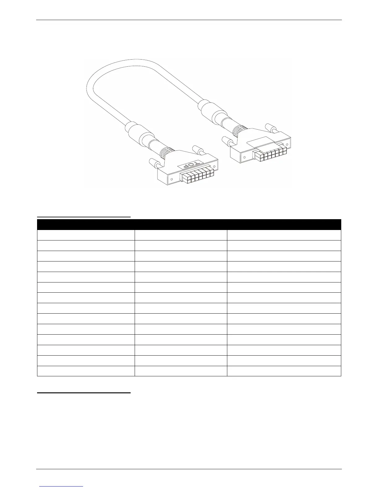
Redundant Power Supply (RPS) Cable
When connecting the Switch to a Redundant Power Supply, an RPS cable is necessary. Please review this product
for matching cable pins. The following diagram and table show the standard RPS connector and its pin assignments.
Figure B-3 RPS Cable for DPS-500A (14-pin Power Cable)
RPS Cable – 14 PIN Assignments:
 Loading...