Install the CPEInstallation Guide
............................................................................................................................................................................................................................................................
Issue 1 February 2011
1-3
............................................................................................................................................................................................................................................................
Mounting procedure
There are two ways for mounting the CPE:
• Wall mounting
1. Locate a high position on the wall that is free of obstructions.
2. Connect two screws in the wall 5 cm (2 in.) apart. Do not screw the screws all the
way into the wall.
Important! Make sure that the screws are securely fixed to the wall and strong
enough to hold the weight of the CPE.
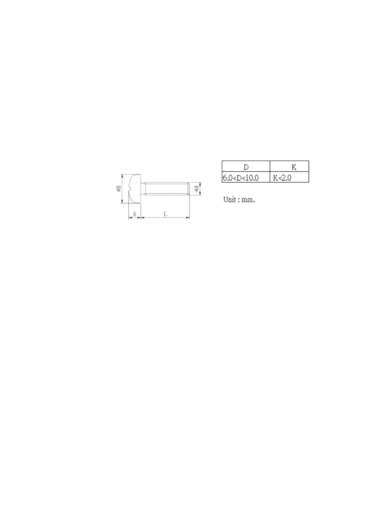
screws specification for wall mounting:
3. Align the holes on the back of the CPE with the screws on the wall.
4. Hang up the CPE on the screws.
• Desktop mounting
Place the CPE on top of the desk with the name logo side up.
HW installation procedure
CAUTION:
Please follow the directions from your service provider regarding the connection of your
VDSL2 bridge. The following procedure are meant as a guideline.
........................................................................................................................................................................................................................
1 Connect the cord of the AC power adapter to the power socket on the CPE which is
labeled 15 V 1 A. Then plug the power adapter directly into the AC power outlet.
Result: The LED (marked power) on the LED panel is on.
........................................................................................................................................................................................................................
2 Restore this CPE to factory defaults if necessary. See section Reset switch to restore the
CPE to the factory defaults.
........................................................................................................................................................................................................................
3 Connect one end of the attached standard telephone cable to the port on the CPE which is
labeled VDSL and connect the other end to the telephone wall outlet providing the VDSL
servive.