xStack® DGS-3420 Series Layer 2+ Managed Stackable Gigabit Switch Hardware Installation Reference Guide
48
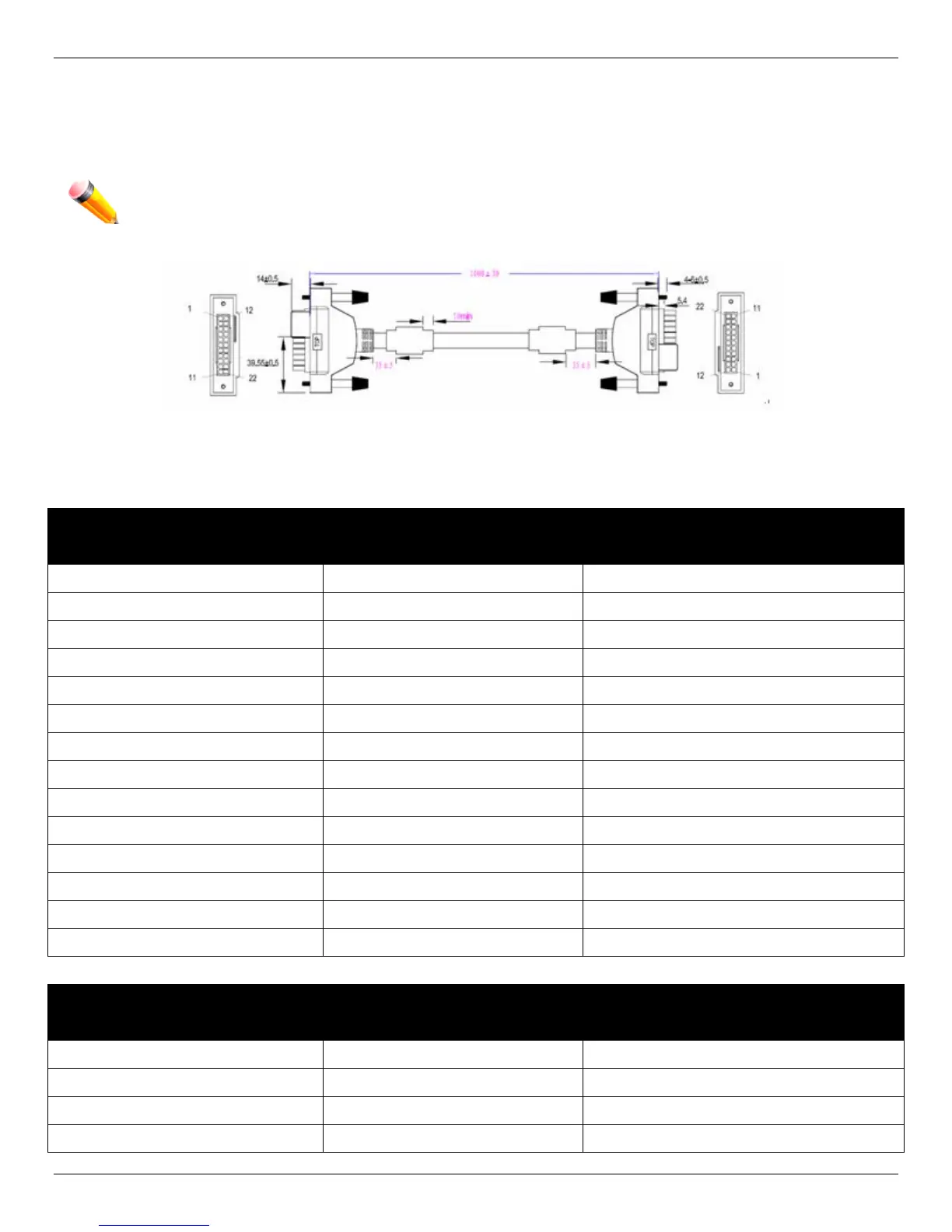
Redundant Power Supply (RPS) Cable
When connecting the Switch to a Redundant Power Supply, an RPS cable is necessary. Please review these products for
matching cable pins.The following diagrams and tables show the standard RPS connector and their pin assignments.
NOTE: The DGS-3420-28PC and the DGS-3420-52P use the RPS-700 and not the RPS-500. Both devices
have their own cables included in the package.
Figure 5–5 Redundant Power Supply (RPS) Cable – DPS-500/DPS-700
RPS Cable Pin Assignments
Pin Device DPS-500
1
GND GND
2
NC NC
3
+12V +12V
4
+12V +12V
5
+12V +12V
6
+12V +12V
7
GND GND
8
GND GND
9
NC Power Good
10
NC Power Present
11
Power Good NC
12
Power Present NC
13
GND GND
14
GND GND
RPS Cable Pin Assignments
Pin Device DPS-700
1
-54Vrtn -54Vrtn
2
-54V -54V
3
+12V +12V
4
+12V +12V