EasyManua.ls Logo

DAB ACTIVE DRIVER T/T 3.0 - User Manual

DAB ACTIVE DRIVER T/T 3.0
10 pages
Print Icon
To Next Page IconTo Next Page
Loading...
1
25/9/08
ACTIVE DRIVER
INTRODUCTION
The DAB ACTIVE DRIVER is an innovative integrated pump control system that utilizes a
variable frequency drive controller (VFD) to provide CONSTANT PRESSUE regardless of the
demand flow requirements.
>Applications
The DAB ACTIVE DRIVER will fit to most DAB domestic pump, specifically Jet, JINOX, JECOM,
EURO, EUROINOX, EUROCOM, K Series and KVCX Vertical Multistage.
The unit is available if the following configurations,
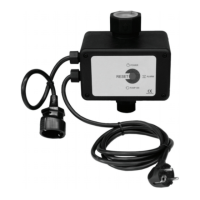
ACTIVE DRIVER M/M 1.1
Suits single phase 230v power supply, and will couple to single phase pump units up to
1.1kW, and is programmable to a maximum pressure of 6 Bar (600kPa), not exceed a
flow of 300lpm.
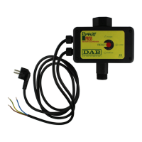
ACTIVE DRIVER M/T 1.0
Suits single phase 230v power supply, and will couple to three phase pump units up to
1.0kW, and is programmable to a maximum pressure of 9 Bar (900kPa), not exceed a
flow of 300lpm.
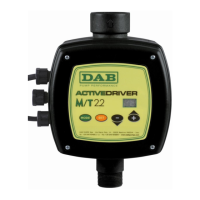
ACTIVE DRIVER M/T 2.2
Suits single phase 230v power supply, and will couple to three phase pump units up to
2.2kW, and is programmable to a maximum pressure of 9 Bar (600kPa), not exceed a
flow of 300lpm.

INVERTER
CONTROLLED

Other manuals for DAB ACTIVE DRIVER T/T 3.0

Questions and Answers

DAB ACTIVE DRIVER T/T 3.0 Specifications

General IconGeneral
Protection degreeIP55
CategoryController
TypeInverter
ApplicationPumps
Frequency50/60 Hz

Summary

INTRODUCTION

Applications

Lists compatible DAB domestic pumps and configurations available.

Selecting the Correct Pump

Explains how to choose the correct pump for the ACTIVE DRIVER based on duty point.

Installing the ACTIVE DRIVER

Details the correct installation position, check valve, and energy saver.

Programming

ESSENTIAL INFORMATION

Lists key information required for programming the unit.

Normal Display Indications

Explains the standard indicators shown on the LCD screen during normal operation.

Displays of the Main Values

Details how to access and interpret key operational data from the display.

Other Displays

Describes how to view additional operational information and system status.

Pump Start Up

Outlines the initial steps for starting the pump after installation and priming.

Inputting Data

Explains how to input essential pump parameters like set point and rated current.

ROTATION

Describes how to change the motor's direction of rotation via the controller settings.

FREQUENCY

Explains the setting for the motor's nominal frequency.

OPERATING MODE

Details how to set the operating mode, referencing the pressure cell.

RESTART PRESSURE

Describes the setting for pressure drop before the pump restarts.

INTERCONNECTION ADDRESS

Explains setting the address for units in a multiple pump system.

ENABLING THE BOOSTER

Details how to activate alternating function in multi-pump systems.

Resetting Error Conditions

Lists error indications and the system's automatic reset attempts for malfunctions.

Resetting Factory Settings

Explains how to restore default settings and lists error conditions and factory parameters.

SYNTHETIC START-UP PROCEDURE

Provides a condensed guide for basic operation setup and parameter configuration.

Related product manuals