18
PMOR30B
PMOR30R
PMOR30S
TEST PROCEDURES
PROCEDURE
LETTER
COMPONENT TEST
Description of main parts
SYMBOL PART NAME FUNCTION
C11, C12 High voltage capacitor High voltage capacitor for doubler circuit.
C2 Film capacitor To smooth line ripple
C3 Film capacitor Capacitor for resonant
CT1 Current transformer To detect power current
D1 Bridge Diode To rectify full-wave of power supply
D11, D12 High voltage diode Full wave voltage doubler
IC1 Integrated Circuit (IC) Inverter circuit controller
L2 Choke Coil To smooth line ripple
Q1 Transistor Power transistor for switching
Q2, Q3 Transistor To drive transistor Q1 ON-OFF
T1 High voltage transformer assembly High voltage transform for high frequency
Test procedure
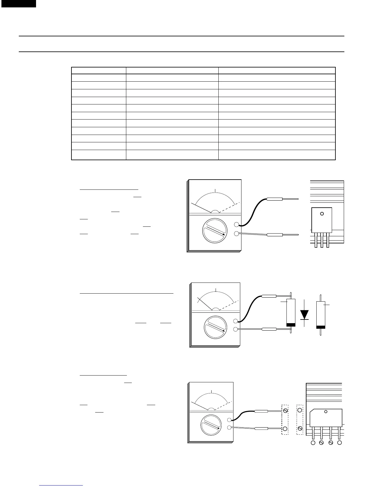
1. Power transistor Q1
Check the transistor Q1 by using ohm-
meter as shown in Figure B-2
If transistor Q1 is defective exchange
Q1.
Check the bridge diode D1, transistor
Q2 and transistor Q3 by using ohm-
meter and replace them if they are
defective.
NOTE: When a digital ohmmeter is
used, reverse the connection
of ohmmeter leads against
Figure B-2.
2. High voltage diode D11 and D12
Check these diodes by using ohmme-
ter as shown in Figure B-2.
If one of the diode is shorted, ex-
change both diodes D11 and D12.
NOTE: When a digital ohmmeter is
used, reverse the connection
of ohmmeter leads against
Figure B-3.
Figure B-3. Check for high voltage diode D11 & D12
3. Bridge diode D1
Check the diode D1 by using ohmme-
ter as shown in Figure B-4.
If the diode D1 is defective, exchange
D1 and power transistor Q1 at same
time (Q1 is defective)
NOTE: When a digital ohmmeter is
used, reverse the connection
of ohmmeter leads against
Figure B-4.
Figure B-4. Check for bridge diode D1.
+
0
∞
20
OK NG
x 1Ω
OK: Normal
NG: Defect
GCE
(G, E)
(C)
Q1
-
UX-F0B
D11
UX-F0BL
D12
Anode
Cathode
+
0
∞
20
OK
NG
x 1Ω
OK: Normal
NG: Defect
-
Yelow
color
White
color
Figure B-2. Check for Power Transistor Q1
 Loading...