28
PMOR30B
PMOR30R
PMOR30S
DESCRIPTION OF LSI
LSI(IZA958DR)
The I/O signal of the LSI(IZA958DR) is detailed in the following table.
Pin No. Signal I/O Description
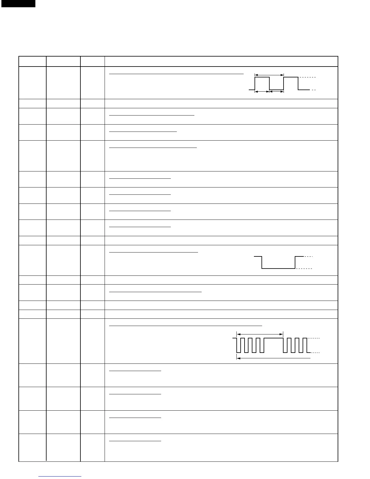
1 TIOCA2 OUT Power level data output signal for inverter unit.
The power level will be decided by the time ratio
of T1 and T2.
2 A20 OUT Terminal not used.
3 Vcc IN Power source voltage : +5.0V.
The power source voltage to drive LSI is input to Vcc terminal. Connected to Vcc.
4 TMO0 OUT Signal to sound buzzer.
A: key touch sound (short beep). B: Completion sound (melody or long beep).
5 PB1 IN Signal coming from touch key.
When either G11 line on key matrix is touched, a corresponding signal out of P93, P94,
P95, P40, P41, P42, P43 and P44 will be input into PB1. When no key is touched, the
signal is held at "H" level.
6 PB2 IN Signal similar to PB1.
When either G12 line on key matrix is touched, a corresponding signal will be input into PB2.
7 PB3 IN Signal similar to PB1.
When either G13 line on key matrix is touched, a corresponding signal will be input into PB3.
8 PB4 IN Signal similar to PB1.
When either G6 line on key matrix is touched, a corresponding signal will be input into PB4.
9 PB5 IN Signal similar to PB1.
When either G5 line on key matrix is touched, a corresponding signal will be input into PB5.
10 PB6 OUT Terminal not used. Connected to test point.
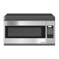
11 PB7 OUT Turntable motor driving signal.
To turn on and off relay(RY2). "H" level: During
Turntable On. "L" level: During Turntable OFF or
during the oven is off condition.
12 RESO OUT Terminal not used.
13 Vss IN Power source voltage: GND(0V).
The power source voltage to drive LSI is input to Vss terminal.
14 TxD0 OUT Data signal is output to a memory IC (IC4).
15 P91 OUT Clock signal is output to a memory IC (IC4).
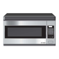
16 RxD0 OUT Oven lamp, fan motor and stirrer motor driving signal
To turn on and off shut off relay (RY1). The
square waveform voltage is delivered to the
RY1 driving circuit.
17 P93 OUT Key strobe signal.
Signal applied to key unit section. A pulse signal is input to PB1-PB5 terminal while one
of G1 line keys on key matrix is touched.
18 P94 OUT Key strobe signal.
Signal applied to key unit section. A pulse signal is input to PB1-PB5 terminal while one
of G2 line keys on key matrix is touched.
19 P95 OUT Key strobe signal.
Signal applied to key unit section. A pulse signal is input to PB1-PB5 terminal while one
of G3 line keys on key matrix is touched.
20 P40 OUT Key strobe signal.
Signal applied to key unit section. A pulse signal is input to PB1-PB5 terminal while one
of G14 line keys on key matrix is touched.
16.7 msec.
T1
T2
H : +5V
L : GND
16.7 msec.
During cooking
H : +5V
L : GND
ON
OFF
H : +5V
L : GND