30
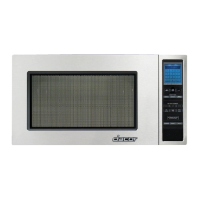
PMOR30B
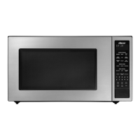
PMOR30R
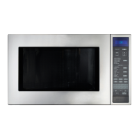
PMOR30S
Pin No. Signal I/O Description
69 XTAL IN Internal clock oscillation frequency control input setting.
The internal clock frequency is set by inserting the ceramic filter oscillation circuit with
respect to XTAL.
70 Vcc IN Power source voltage : +5V.
The power source voltage to drive LSI is input to Vcc terminal. Connected to VCC.
71 AS OUT Terminal not used.
72 RD OUT Read strobe signal is output to RD terminal of IC5.
73 HWR OUT Write strobe signal is output to WR terminal of IC5.
74 LWR OUT Terminal not used.
75-76 MD0-MD1 IN Connected to VCC.
77 MD2 IN Connected to GND.
78 Avcc IN A/D converter power source voltage : +5V.
The power source voltage to drive the A/D converter. Connected to VCC.
79 Vref IN A/D converter power source voltage : +5V.
The power source voltage to drive the A/D converter. Connected to VCC.
80 AN0 IN When a magnetron generates abnormally the detecting signal is input to AN0 terminal.
81 AN1 IN To input signal which communicates the door open/close information to LSI.
Door close "L" level signal (GND). Door open "H" level signal (+5V).
82 AN2 IN Terminal to change cooking input according to the model.
By using the A/D converter contained in the LSI, DC voltage in accordance with the
Model in operation is applied to set up its cooking constant.
83 AN3 IN Terminal to judge whether the model has the sensor cooking function or not.
By using the A/D converter contained in the LSI, DC voltage in accordance with the
Model in operation is applied to judge whether the model has the sensor cooking
function or not.
84 AN4 IN AH sensor input.
This input is an analog input terminal from the AH sensor circuit, and connected to the
A/D converter built into the LSI.
85 AN5 IN Used for initial balancing of the bridge circuit (absolute humidity sensor). This input is
an analog input terminal from the AH sensor circuit, and connected to the A/D converter
built into the LSI.
86 DA0 OUT Terminal not used.
87 DA1 OUT The signal for the power source to drive the LCD is output to IC3.
88 Avss IN A/D converter power source voltage : GND(0V).
The power source voltage to drive the A/D converter. Connected to GND.
89 IRQ0 IN Signal synchronized with commercial power source frequency.
This is the basic timing for time processing of
LSI.
90-91 P81-P82 OUT Terminal not used.
92 CS1 OUT Chip select signal is output to CS terminal of IC5.
93 CS0 OUT Chip select signal is output to CE terminal of IC2.
94 Vss IN Power source voltage : GND (0V).
The power source voltage to drive the LSI is input to Vss terminal.
95-99 PA0-PA4 OUT Used for initial balancing of the bridge circuit (absolute humidity sensor).
100 PA5 OUT Clock signal is output to IC5.
16.7 msec.
H : +5V
L : GND