21
TDA4665(Base Band Delay Line)
(1) Features
• Two comb filters, using the switched-capacitor technique,for one line delay time (64µs)
• Adjustment free application
• No crosstalk between SECAM colour carriers
• Handles negative or positive colour-difference input signals
• Clamping of AC-coupled input signals(±(R-Y)and±(B-Y))
• VCO without external components
• 3MHz internal clock signal derived from a 6MHz VCO, line-locked by the sandcastle pulse (64µs line)
• Sample-and -hold circuits and low-pass filters to suppress the 3 MHz clock signal
• Addition of delayed and non-delayed output signals
• Output buffer amplifiers
• Comb filtering functions for NTSC colour-difference signals to suppress cross-colour
(2) General Description
The TDA4661 is an integrated baseband delay line circuit with one line delay. It is suitable for decoders
with colour-difference signal outputs±(R-Y)and±(B-Y).
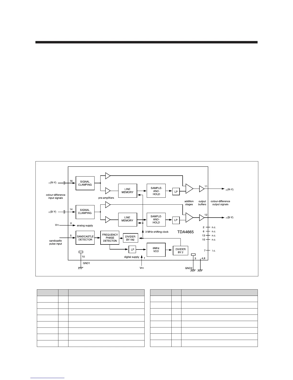
(3)Block Diagram
(4) Pin Description
SYMBOL PIN DESCRIPTION
Vp2 1 +5V supply voltage for digital part
n.c. 2 not connected
GND2 3 ground for digital part (0V)
i.c. 4 internally connected
SAND 5 sandcastle pulse input
n.c. 6 not connected
i.c. 7 internally connected
i.c. 8 internally connected
SYMBOL PIN DESCRIPTION
Vp1 9 +5V supply voltage for analog part
GND1 10 ground for analog part (0V)
V0 (R-Y) 11 ± (R-Y) output signal
V0 (B-Y) 12 ± (B-Y) output signal
n.c. 13 not connected
V1 (B-Y) 14 ± (B-Y) input signal
n.c. 15 not connected
V
1 (R-Y) 16 ± (R-Y) input signal