p04.tif
4 ELECTRICALS
NEXIA,
CIELO,
RACER
II
A. GENERAL DESCRIPTION
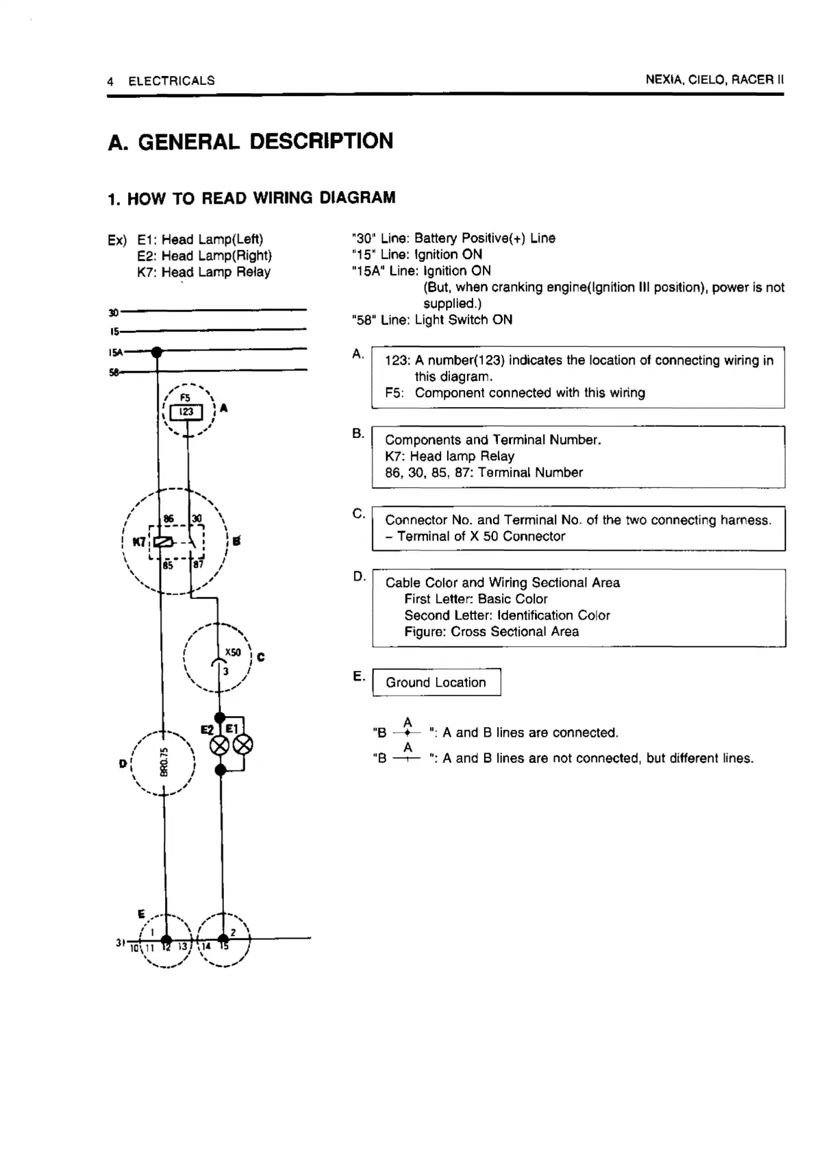
1. HOW TO READ WIRING DIAGRAM
Ex)
E1
: Head Lamp(Left)
E2:
Head Lamp(Right)
K7:
H~d
Lamp Relay
30----------
J§A---r--------
,,"
,,
, '
I •
30
\
, I"'
---
.,
\
I I I I
I
KT,
- :
,•
\ t -
·-
'rl/
,,
'
15,
,/
,,
,,
"''
,,,.-
l
D'
I
\
'
,_
31
10\
11
·,_
"30" Line: Battery Positive(+) Line
•15• Line: Ignition
ON
·1sA
0
Line: Ignition ON
(But, when cranking englne(lgnltion Ill position), power Is not
supplled.)
·ss·
Line: Light Switch
ON
A.
B.
C.
D.
123: A number(123) Indicates the location
of
connecting wiring in
this diagram.
F5: Component connected
with
this wiring
Components and Termlnal Number.
K7: Head lamp Relay
86, 30, 85, 87: Terminal
Number
Connector No. and Terminal No.
of
the two connecting hamess.
-Terminal
of X 50 Connector
Cable Color and Wiring Sectional Area
First Letter: Basic Color
Second Letter: Identification Color
Figure: Cross Sectional Area
E. , Ground Location
j
·e
--i-
":
A and B lines
are
connected.
A
·e
-,-
":
A and B lines are not connected, but different lines.