5. FM DEVIATION
1) Confirm that the adjustment for the playback Y-Signal output level has been made corretly.
2) Feed the color bar signal to the line terminal, and set the VCR to the record mode.
3) Connect the oscilloscope to TP396 and trigger the scope with a composite sync signal (TP313).
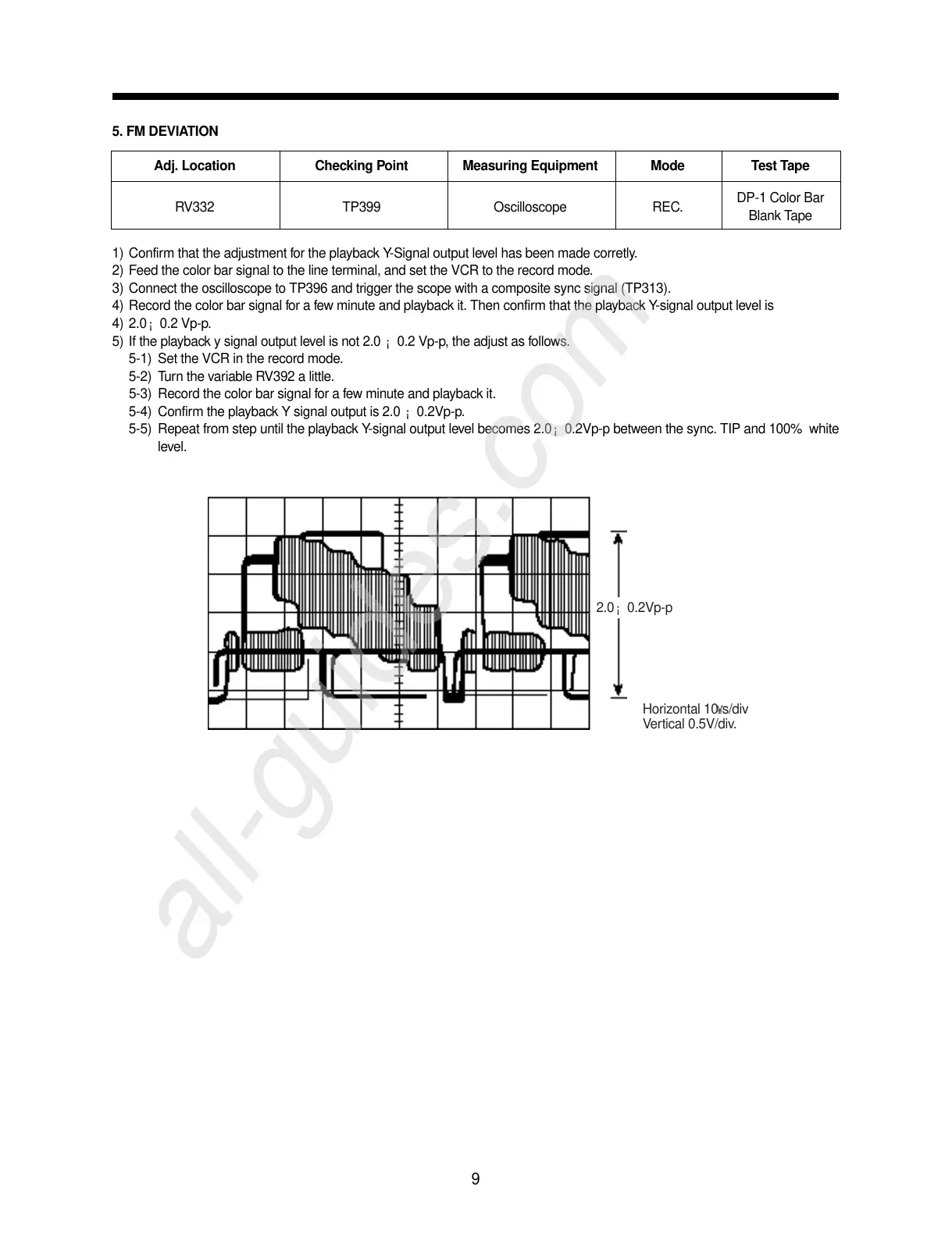
4) Record the color bar signal for a few minute and playback it. Then confirm that the playback Y-signal output level is
4) 2.0¡ 0.2 Vp-p.
5) If the playback y signal output level is not 2.0 ¡ 0.2 Vp-p, the adjust as follows.
5-1) Set the VCR in the record mode.
5-2) Turn the variable RV392 a little.
5-3) Record the color bar signal for a few minute and playback it.
5-4) Confirm the playback Y signal output is 2.0 ¡ 0.2Vp-p.
5-5) Repeat from step until the playback Y-signal output level becomes 2.0¡ 0.2Vp-p between the sync. TIP and 100% white
level.
9
Adj. Location Checking Point Measuring Equipment Mode Test Tape
RV332 TP399 Oscilloscope REC.
DP-1 Color Bar
Blank Tape
2.0¡ 0.2Vp-p
Horizontal 10¥s/div
Vertical 0.5V/div.