16
1. Mechanical Adjustment (Fig. 4.1~4.4)
In case of deassembly and reassembly for fixing the mechan-
ical problem, check the following check point.
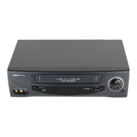
a. Make sure that the DATUM HOLE of the CAM GEAR is
aligned with the DATUM HOLE in the MAINBASE in
the EJECT mode as shown in Fig. 4.1.
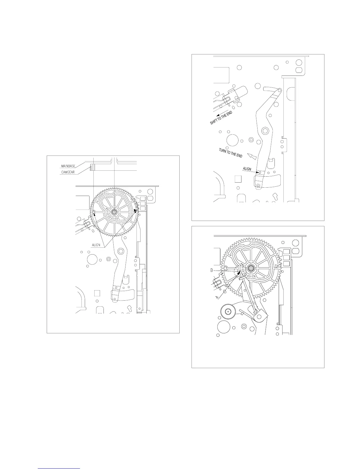
b. Make sure that the ending part “A” of the RELAY
LEVER assembled on the CONNECT PLATE is aligned
with the reference hole “B” of the MAINBASE as shown
in Fig. 4.2.
c. The end point “A” of PINCH SPRINGPING of the
LEVER TOTAL Ass’y should be located within the tra-
jectory “B” of the CAM GEAR. (Fig. 4.3)
MECHANICAL ADJUSTMENT
FIg. 4.1 Assembly reference between the FL RACK and the
CAM GEAR
FIg. 4.2 Assembly reference between the RELAY LEVER
and the CAM GEAR
FIg. 4.3 Assembly reference of the PINCH LEVER TOTAL
ASS’Ywith the CAM GEAR
 Loading...