Do you have a question about the Dahua DHI-KTA01 and is the answer not in the manual?
Details on where and how to install the device to ensure proper operation and prevent damage.
Specifies the type of power supply and wiring needed, including voltage and safety standards.
Overview of the analog 4-wire video intercom system and its application.
Details the functionalities of both the video intercom and voice intercom components.
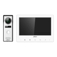
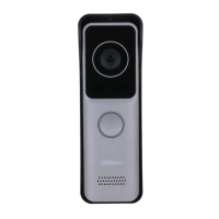
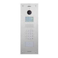
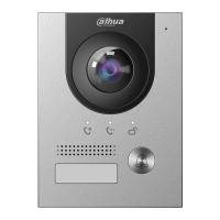
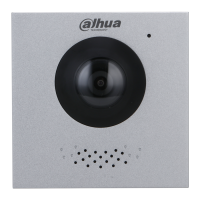
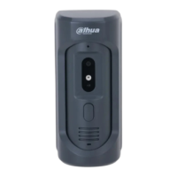
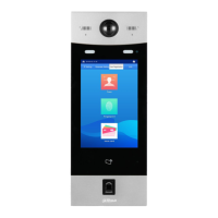
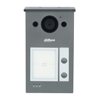
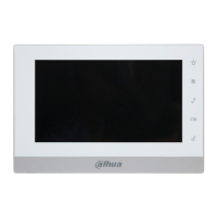
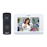
Illustrates the physical appearance of the video and voice intercom units.
Explains the icons and buttons on the front panel of the video intercom.
Details the ports and connections available on the rear panel of the video intercom.
Instructions for mounting the video intercom and voice intercom units on the wall.
Information on port connection rules and selecting appropriate cord specifications for wiring.
Guidance on connecting the intercom system, including safety precautions and system capacity.
This document describes an Analog 4-Wire Video Intercom system, which comprises both voice intercoms and video intercoms. It is designed for use in buildings, such as residential buildings, to facilitate voice and video communication between residents and visitors. The voice intercom is typically installed outdoors, while the video intercom is installed indoors.
The Analog 4-Wire Video Intercom system enables real-time voice and video communication. The video intercom can connect to up to three voice intercoms and also supports connection to external cameras (CVBS). The voice intercoms feature a built-in camera and self-adaptive IR fill light, allowing them to send phone calls to video intercoms.
The system offers intuitive controls for managing communication and settings. On the video intercom's front panel, dedicated buttons allow users to adjust speaker volume during video/voice communication: one button decreases the volume, and another increases it.
When the video intercom rings, pressing a specific button allows the user to initiate voice communication with the person at the voice intercom. Pressing this button twice quickly enables hanging up a call from the voice intercom. Another button allows the user to view the person at the voice intercom and engage in conversation. Repeated presses of this button cycle through real-time video feeds: first from one voice intercom, then a second, and finally from an analog camera, if connected.
A dedicated button is also available to open the door near the voice intercom when it is ringing. The video intercom includes an LCD screen for display, a power indicator, and a silent indicator. During communication, pressing the silent button will mute the video intercom, and the indicator will turn off. Both the video and voice intercoms feature microphones and speakers for audio communication. The voice intercom also has a built-in camera and a call button. A water outlet is present on the voice intercom to allow liquid to drain from the speaker.
The system uses RVV4 cords for wiring, with specific cord specifications depending on the transmission distance between the voice and video intercoms:
The system supports a maximum configuration of two voice intercoms and three video intercoms within a single communication system.
The video intercom's rear panel includes several connection points:
The port connection rules are crucial for proper data communication:
The recommended analog cameras (CVBS) for this system are from the HAC 1230 series.
The video intercom is installed by first fixing a bracket to the wall with screws, and then hanging the video intercom onto this bracket. The voice intercom can be installed in two ways: either by fixing its bracket to the wall and then hanging the voice intercom on it, or by installing a voice intercom cover on the wall and then hanging the voice intercom onto the cover.
The document emphasizes several safety instructions and operating requirements to ensure proper functioning and longevity of the device:
The document also notes that the guide is for reference only, and the actual product prevails in case of inconsistency. Designs and software are subject to change without prior notice, and users should contact customer service for the latest information.
| Brand | Dahua |
|---|---|
| Model | DHI-KTA01 |
| Category | Intercom System |
| Language | English |