Do you have a question about the Dahua DHI-VTO4202F Series and is the answer not in the manual?
| Main Processor | Embedded processor |
|---|---|
| Operating System | Embedded LINUX |
| Camera | 2 MP CMOS high definition, wide angle fisheye camera |
| Video Compression | H.264 |
| Resolution | 1080P (1920x1080); 720P (1280x720); D1 (704x576) |
| Video Bit Rate | 256 Kbps to 4 Mbps |
| Lens | 2.0 mm |
| Day/Night | ICR auto switch |
| Audio Compression | G.711a; G.711Mu; PCM |
| Audio Input | 1 |
| Audio Output | 1 |
| Audio Mode | Two-way audio |
| Audio Gain | AGC; Digital Echo Suppression; Digital Noise Reduction |
| Ethernet | 10 M/100 M Ethernet |
| Network Protocol | TCP/IP |
| RS485 | 1 |
| Alarm Input | 2 (Switching value input) |
| Alarm Output | 1 (Relay output) |
| Card Reader | 1, IC card |
| Tamper Switch | 1 |
| Electric Lock | 1 |
| Door Status Detection | 1 |
| Exit Button | 1 |
| Lock Control | 1 |
| Network | RJ-45 (10/100Base-T) |
| Power Input | 12VDC 1A |
| Casing Material | Aluminum alloy |
| Installation | Surface mount |
| Power Supply | 12VDC 1A |
| IP Rating | IP65 |
| Tamper-proof | Support |
| Weight | 0.48 kg (1.06 lb) |
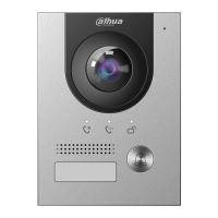
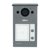
Front and rear panel details of the camera module, including MIC, Camera, Speaker, and ports.
Description of the various ports on the intercom module for power, locks, Ethernet, and cascade connections.
Details the front and rear panel indicators for call, talk, and unlock status, along with cascade connections.
Explains the front and rear panel of the five-button call panel, including user directory and call buttons.
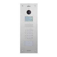
Details the front panel keypad with selection, numbers, place call, and call management center functions.
Illustrates the IC Card Reader module and its rear panel cascade input/output connections.
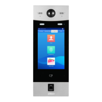
Shows the fingerprint reader module and its rear panel cascade input/output connections.
Details the information text display module and its rear panel cascade input/output connections.
Explains the purpose of the blank module for covering extra space when no other functional modules are needed.
Provides instructions on how to make cascade connections between intercom modules, emphasizing input/output port usage.
Instructions on how to log in to the VTO interface using username and password after initialization.
Guide to resetting the VTO password via email security code or by contacting support if email was not set.
Configuration of basic VTO parameters like device type, name, center call number, and SD card capacity.
Setting up main and sub-stream video formats, frame rates, bitrates, and audio control options.
Configuration of local access control parameters for door locks, sensors, and unlock commands.
Configuration of time parameters, NTP server, and other system-wide settings.
Configuration of functions that involve device security, such as CGI, push notifications, and encryption.
Configuration for Wiegand port parameters when connecting devices like card readers.
Adding accounts for ONVIF devices to monitor the VTO, including username and password setup.
Uploading audio files to customize sound prompts for events like calling or unlocking doors.
Adding VTOs to the SIP server to enable communication between connected devices.
Managing VTH devices, including adding room numbers and issuing access cards or fingerprints.
Adding a VTS to the SIP server to use it as the management center for VTOs and VTHs.
Adding IP cameras and NVRs to the VTO for monitoring by connected VTH monitors.
Viewing the online status and IP addresses of all connected devices on the network.
Sending messages from the SIP server to VTH devices and viewing message history.
Configuring IP address, subnet mask, default gateway, and DNS for the VTO's network connection.
Configuring UPnP to allow WAN devices to log in to the VTO when it acts as a SIP server.
Setting up a SIP server for VTOs and VTHs to call each other, either using a VTO or another server.
Enabling and configuring firewall types to control network access to the VTO.