This document describes a modular door station, referred to as "VTO," designed for various access control and communication applications. The VTO system is highly flexible, allowing users to build custom configurations with different modules to suit specific needs.
Function Description
The VTO serves as a central component in an intercom or access control system, facilitating communication and entry management. Its primary functions include:
- Video Call: Enables video calls to indoor monitors (VTHs).
- Group Call: Supports calling multiple VTHs simultaneously.
- Video Monitoring: Allows up to 6 VTHs to view the monitoring image of the VTO at the same time.
- Emergency Call: Facilitates calls to a management center during emergencies.
- Unlock: Supports unlocking doors using cards, fingerprints, or passwords.
- Alarm: Features anti-tampering alarms, door contact alarms, and duress password unlock alarms, with alarm information sent to a management center.
- Record Search: Provides functionality to search call records, alarm records, and unlock records.
The modular design allows for a wide range of configurations, integrating different functionalities into a single system. The core camera and audio modules are indispensable, while other modules can be added as needed.
Important Technical Specifications
The VTO system supports various modules, each with specific components and interfaces:
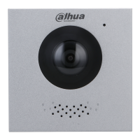
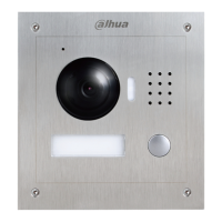
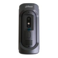
Camera Module (VTO4202F-MK, VTO4202F-MB1, VTO4202F-MB2, VTO4202F-MB5, VTO4202F-MR, VTO4202F-MS, VTO4202F-MF, VTO4202F-ML, VTO4202F-MA, VTO4202F-P, VTO4202F-P-S2):
- Front Panel: Includes a microphone, camera, and speaker.
- Rear Panel: Features an anti-tampering switch (triggers an alarm if the VTO is forcibly removed), ports for power supply, electric control lock, solenoid lock, and exit button, an Ethernet port for network connection, and a cascade connection port for linking to other modules.
- Ports: Detailed port descriptions include GND, +12V_OUT, RS-485_B, RS-485_A, ALARM_NO, ALARM_COM, EOC1 (2-wire GND for camera module), DOOR_BUTTON, DOOR_FEEDBACK, DOOR_NC, DOOR_COM, and EOC2 (2-wire +48V for camera module), and DOOR_NO.
Indicator Module:
- Front Panel: Displays call, talk, and unlock indicators, providing visual feedback on activity status.
- Rear Panel: Equipped with cascade input and output ports for connecting to other modules.
Audio Module:
- Front Panel: Contains a microphone and speaker.
- Rear Panel: The rear panel configuration is identical to the camera module, suggesting shared connectivity features for cascade and power.
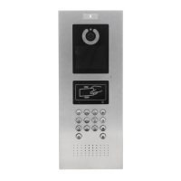
Button Module (One-button, Two-button, and Five-button options):
- Front Panel: Features a user directory for name cards and call buttons.
- Rear Panel: Includes cascade input and output ports.
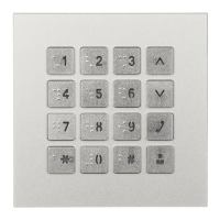
Keyboard Module (with Braille):
- Front Panel: Comprises selection buttons, number keys (for entering passwords or VTH numbers), a call button (to call VTHs), and a call management center button.
- Rear Panel: Shares the same configuration as the button module, with cascade input and output ports.
Card Module:
- Front Panel: Features an icon for card swiping.
- Rear Panel: The rear panel configuration is identical to the button module.
Fingerprint Module:
- Front Panel: Designed to collect and verify fingerprints.
- Rear Panel: While port positions differ from the button module, the port functions are the same.
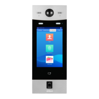
Display Module:
- Front Panel: Displays user information.
- Rear Panel: Similar to the fingerprint module, port positions differ from the button module, but port functions are the same.
Blank Module:
- Used to fill extra space when assembling modules, improving the overall aesthetic.
Cascade Connection:
- All modules require cascade connection to function together, ensuring seamless integration and communication within the system.
Usage Features
The VTO is designed for ease of configuration and commissioning, supporting both villa and small apartment scenarios.
Configuration Procedure:
- Planning: Plan IP addresses and unit/room numbers for each device.
- VTO Configuration:
- Initialization: Power on the VTO, access its IP address in a browser (default 192.168.1.108 for first-time login), and create a new password. It is recommended to change the default IP address to avoid conflicts if multiple VTOs are present.
- VTO Number: Configure a unique VTO number (up to 6 digits, alphanumeric). This number is crucial for distinguishing VTOs and for SIP server functionality.
- Network Parameters: Set TCP/IP information such as IP address, subnet mask, and default gateway. The VTO will restart after saving these changes.
- SIP Servers: Configure SIP server settings. The VTO can act as a SIP server for a single building, or connect to an external platform (Express/DSS) for multiple buildings/units. Parameters include SIP server IP address, port, username/password, SIP domain, and alternate server settings.
- Adding VTO: If using an external SIP server, add the VTO to the server by specifying its number, IP address, and login credentials.
- Adding Room Number: For VTOs acting as SIP servers, room numbers can be added (up to 6 digits, alphanumeric).
- Villa Station: Set Device Type to "Villa Station" and manage VTHs by adding room numbers. Main VTHs end with #0, and sub VTHs with #1, #2, etc., supporting up to 10 sub VTHs per main VTH.
- Small Apartment: Set Device Type to "Small Apartment" and configure room numbers individually or in batches, specifying unit layer amount, room amount per layer, first floor number, and second floor number.
- Configuring Modules: Add and configure functional modules (e.g., button, card, fingerprint) to the facade layout. The VTO supports up to 9 functional modules, with only one of each type for fingerprint, card, and keyboard modules. Room numbers can be assigned to buttons on the button module.
Commissioning:
- VTO Calling VTH: Dial a room number on the VTO, and the VTH will ring. Tap the answer button on the VTH to establish the call.
- VTH Monitoring VTO: On the VTH, select "Monitor > Door" to view the VTO's camera feed.
Maintenance Features
- Device Update: Firmware and client software updates are crucial for security patches and fixes. Users are advised to keep devices up-to-date and enable "auto-check for updates" when connected to a public network.
- Password Management:
- Strong Passwords: Use passwords that are at least 8 characters long, include multiple character types (uppercase, lowercase, numbers, symbols), and avoid common patterns or account names.
- Regular Changes: Change passwords regularly to minimize the risk of unauthorized access.
- Password Reset Information: Set up and timely update password reset information (e.g., mailbox, security questions).
- Account Lock: The account lock feature is enabled by default, locking accounts and source IP addresses after multiple failed login attempts, enhancing security.
- Physical Protection: Physically secure the device and storage devices in a controlled environment to prevent unauthorized access, tampering, or connection of removable devices.
- Network Security:
- HTTPS: Enable HTTPS for secure communication over the web service.
- MAC Address Binding: Bind the IP and MAC address of the gateway to the device to reduce ARP spoofing risks.
- Account and Privileges: Assign appropriate access control permissions and manage them responsibly.
- Unnecessary Services and Secure Modes: Disable unnecessary services and choose secure modes (e.g., SNMPv3, SMTPS, UPnP, SFTP, WPA2-PSK) for essential services.
- Audio and Video Encrypted Transmission: Enable encrypted transmission for audio and video data to prevent data theft during transmission.
- Secure Auditing: Enable online users check and check device logs regularly to monitor for unauthorized access or suspicious activities.
- Network Log: Due to limited storage capacity, the network log function should be enabled only for critical events to ensure that critical logs are synchronized to a network log server for tracing.
- Safe Network Environment:
- Disable port mapping function on the router to prevent direct access from external networks.
- Segment the network into VLANs, network GAP, and other technologies to partition the network and enhance security.
- Enable 802.1x access authentication to reduce the risk of unauthorized access to private networks.
- Enable IP/MAC address filtering to limit the range of hosts allowed to access the device.
- Service Ports: Change default HTTP and other service ports to non-standard numbers (1024-65535) to reduce the risk of outsiders guessing which ports are in use.