English 18
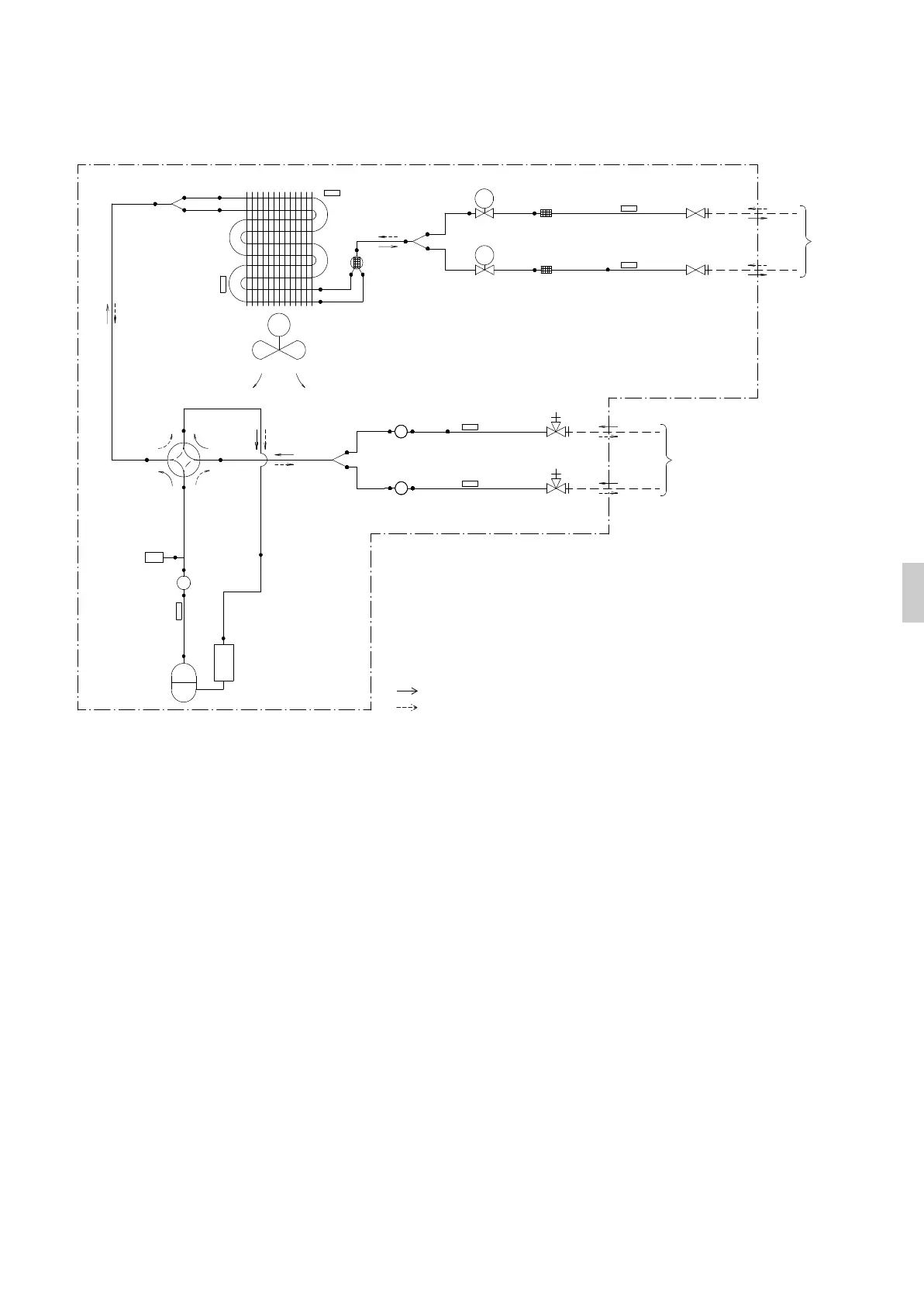
Piping Diagram
Piping diagram for 2MXM50M3V1B9, 2AMXM50M4V1B, 2AMXF50A2V1B
PED categories of equipment - High pressure switches: category IV; Compressor: category II; Other art 4§3 equipment.
Outdoor unit
Heating
Cooling
Refrigerant flow
7.9CuT
7.9CuT
M
4.8CuT
4.8CuT
9.5CuT
7.9CuT
Heat exchanger thermistor
Accumulator
Compressor
4-way valve
Discharge pipe thermistor
Propeller fan
ON: heating
Muffler
9.5CuT
9.5CuT
9.5CuT
Branch pipe
Muffler
Gas stop valve
Muffler
Gas stop valve
9.5CuT
9.5CuT
Thermistor (gas)
Thermistor (liquid)
Thermistor (gas)
6.4CuT
6.4CuT
EV
A
EV
B
Motor-operated valve
9.5CuT
6.4CuT
Thermistor (liquid)
Liquid stop valve
Liquid stop valve
Branch pipe
Branch pipe
6.4CuT
6.4CuT
Fan motor
9.5CuT
Filter
Filter
9.5CuT
HPS1
9.5CuT
Twin-branched muffler
Field piping
Room ·A·
Room ·B·
(9.5CuT)
(12.7CuT)
Gas
Liquid
Field pipi
ng
Room ·A·
(6.4CuT)
Room ·B·
(6.4CuT)
Heat exchanger
Outdoor air temperature thermistor
High pressure switch
Automatic reset
3PEN423316-4P.book Page 18 Wednesday, January 16, 2019 11:27 AM
 Loading...