EasyManuals Logo

Daikin 4MKD90BVM User Manual

Daikin 4MKD90BVM
298 pages
To Next Page IconTo Next Page
To Previous Page IconTo Previous Page
Page #254 background imageLoading...
Page #254 background image
Si12-411A Outdoor Unit (50 / 52 / 58 / 68 / 75 Class)
Removal Procedure 243
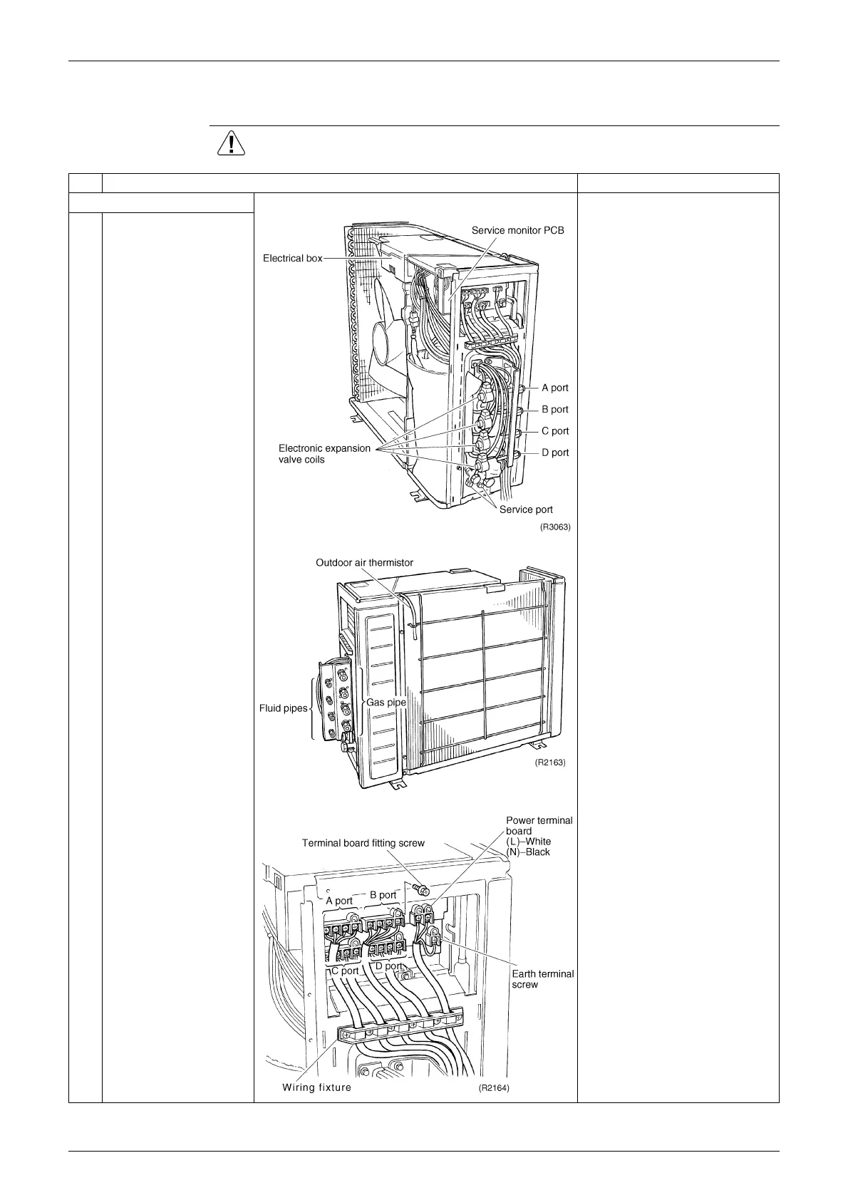
2.2 Removal of Electrical BOX
Procedure Warning Be sure to wait 10 minutes or more after turning off all power supplies
before disassembling work.
Step
Procedure Points
1. Removing the tie wires
Remove the piping in the
backward direction.
1 The figure shows the tie
pipe connections.
2
Remove the terminal
board fitting screw.
Match the colours of the tie
wires to A, B, C and D ports
as follows.
(1) - Black Power
(2) - White Power
(3) - Red Transmission
Wires are fixed to the
terminal board with screws.
Terminal board is made of
integral moulded resin.

Table of Contents

Questions and Answers:

Question and Answer IconNeed help?

Do you have a question about the Daikin 4MKD90BVM and is the answer not in the manual?

Daikin 4MKD90BVM Specifications

General IconGeneral
CategoryAir conditioning
Model4MKD90BVM
Cooling Capacity9.0 kW
Heating Capacity10.0 kW
Energy Efficiency Ratio (Cooling)3.21
Coefficient of Performance (Heating)3.61
Outdoor Unit Dimensions (HxWxD)735x936x300 mm
Power Supply220-240 V, 50 Hz

Related product manuals