Installation and operation manual
16
FWEC3
Advanced plus electr
onic controller
FC66002765
ELECTRONIC BOARD (FIGURE 6)
Wher
e
Vc
Valve
Vh
Heat valve/heater
V0
Extra low speed
V1
Minimum Speed
V2
Medium Speed
V3
Maximum Speed
N
Neutral
L
Phase
PE
Ground
A-B-GND
RS 485
SU
Remote humidity probe
SW
Water sensor
SA
Remote air sensor
101
0-10V 1 Output
COM
0-10V Output Common
102
0-10V 2 Output
DO2
Digital 2 output
DO1
Digital 1 output
CO12
Digital output Common
DI1
Dig.1 input
CI12
DI1-2 Common
DI2
Dig. 2 input
N.B.:
■ For power connections use cable w/ cross section size of
1 mm2
■ For digital inputs used AWG 24 cable
■ For sensor extensions and RS485 use AWG 24 shielded
cable
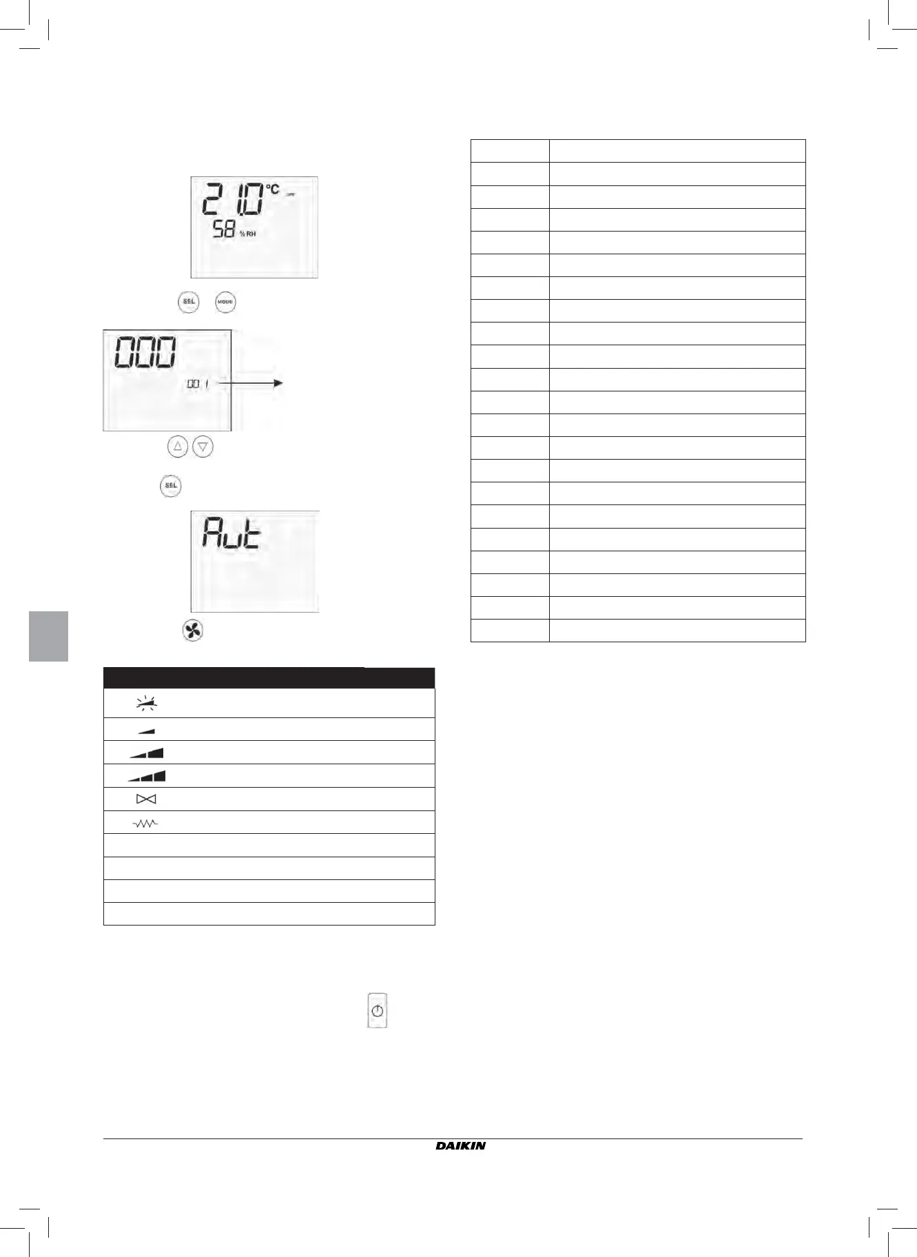
SELF-DIAGNOSIS PROCEDURE
This pr
ocedure allows you to check whether the individual
outputs of the controller function correctly.
To run the procedure, follow the directions below:
■ switch the thermostat off
■ push the
at the same time
■ use the keys to change the value on the display
until arriving at the password for self-diagnosis (030) and
press
. The following scr
een will be displayed:
■ press the
button to switch on the various thermostat
outputs in sequence.
Symbol Actuation
Terminals
Extra low speed
N-V0
Minimum speed
N-V1
Medium speed
N-V2
Maximum speed
N-V3
V
alve N-Vc
Heater / Second valve
N-Vh
CO1 Digital 1 output C012-C01
CO2 Digital 2 output C012-C02
AO1 Analog output 1 = 10V COM-101
AO2 Analog output 2 = 10V COM-102
The electronic controller outputs can be checked one by one
either by observing the respective component (valve, fan..)
or verifying whether a voltage of 230 V is present at the cor-
responding terminals.
■ to exit the self-diagnosis procedure press
(after a
few minutes the thermostat will automatically exit in any
case).
level 1: passwor
d entry