Installation and operation manual
7
FWEC3
Advanced plus electr
onic controller
FC66002765
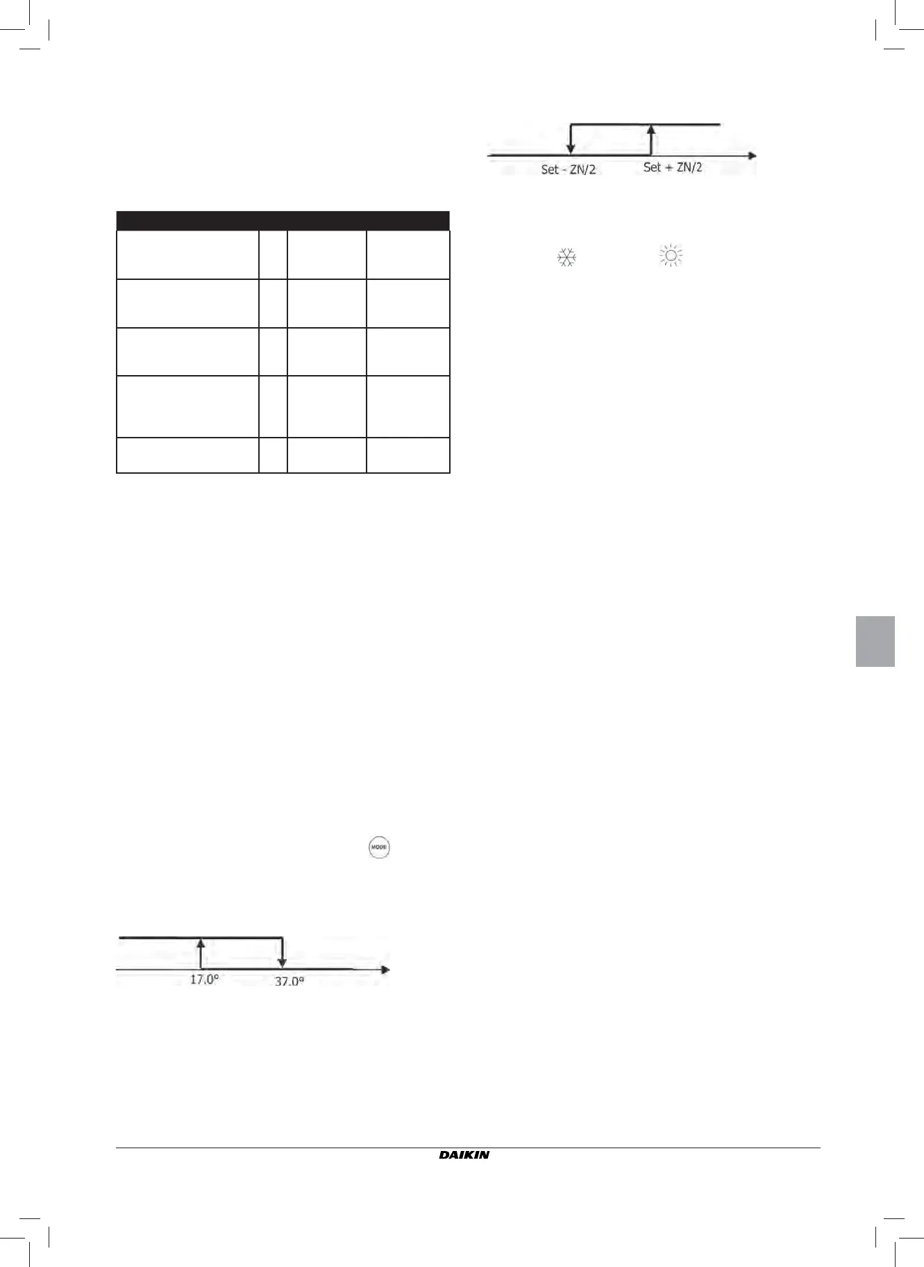
4 depending on air temperatur
e
Dove:
■ Set is the temperature setting made by the arrows
■ ZN is the neutral zone (parameter P03)
The thermostat operating mode is indicated on the display by
the symbols
(cooling) and (heating)
VENTILATION
GENERAL ASPECTS
The contr
oller can perform two types of fan control:
- step control, with a fi xed number of selectable speeds (3
or 4);
- modulating control, with speeds ranging from 0% to
100%
Which type of control will be used clearly depends on the type
of fan (modulating or non modulating) installed in the unit;
the controller makes the selection based on the value set for
confi guration parameter P14. Step control in turn follows two
different logics depending on the type of valve(s) (ON/OFF or
modulating); this information, like the fan type, is deduced by
the controller based on the value taken on by confi guration
parameter P14. Consequently, confi guration parameter P14
must be carefully set in order to ensure that the unit functions
correctly.
Important: in the case of modulating fan control, in order to
achieve a correct adjustment the controller takes
into account the number of speeds implicitly
indicated by the value assigned to confi guration
parameter P00. Though it may seem contradictory
to talk about “number of speeds” in the case of
modulating fan control, this information is essential
for indicating to the control system whether the unit
is designed to work in the natural convection mode
or not. Based on this information, the modulating
fan control will follow different logics.
Summing up, the automatic control logics implemented by the
controller (and described in detail below) are the following:
- step fan control with ON/OFF valve (or valve absent) and
3 speeds, in the cooling and heating modes (specular
logics);
- step fan control with ON/OFF valve (or valve absent) and
4 speeds, in the cooling and heating modes (specular
logics);
- step fan control with modulating valve and 3 speeds, in
the summer and winter modes (specular logics);
- step fan control with modulating valve and 4 speeds, in
the summer and winter modes (non-specular logics);
- modulating fan control with ON/OFF valve, in the summer
and winter modes (specular logics);
- modulating fan control with modulating valve
CONFIGURATION OF 0-10V ANALOG OUTPUTS
(PARAMETER P14)
The table below is a guide to setting parameter P14 corr
ectly
based on the type of valve(s) and fan the unit is equipped
with. For each type of unit an indication is given of which value
should be assigned to parameter P14 and the consequent use
mode of the two analogue outputs.
TYPE OF UNIT
P14 AOUT1 AOUT2
2 OR 4 PIPES UNIT WITH ON/OFF
VALVE AND NON-MODULATING
FAN
0 NOT USED NOT USED
2 PIPES UNIT WITH
MODULATING VALVE AND NON-
MODULATING FAN
1
VALVE
MODULATION
--
2 PIPES UNIT WITH
MODULATING VALVE AND
MODULATING FAN
2
VALVE
MODULATION
FAN
MODULATION
4 PIPES UNIT WITH
MODULATING VALVES
(MODULATING FAN NOT
ALLOWED)
3
COLD WATER
VALVE
MODULATION
HOT WATER
VALVE
MODULATION
2 OR 4 PIPES UNIT WITH ON/OFF
VALVE(S) AND MODULATING FAN
4--
FAN
MODULATION
SERIAL COMMUNICATION
Connection to the RS485 communication network
The communication network (bus type) r
elies on a simple
shielded 2-conductor cable, directly connected to the RS485
serial ports of the controllers (terminals A, B and GND).
For the network use a cable AWG 24 (diam. 0.511 mm)
The communication network must have the following general
structure (fi gure 4):
In the case of the “MASTER-SLAVE” solution a termination
resistor will have to be installed on both controllers at the
furthest ends of the network.
N.B.: (1) Comply with the polarity of the connection: indi-
cated with A(-) and B(+)
(2) Avoid ground loops (ground shield at one end
only)
LOGICS
COOLING/HEATING SWITCHING
Four logics ar
e present to select the thermostat operating
modes according to the controller confi guration setting pa-
rameter P00):
1 Local: user choice made through the key
2 Distance: depending on the Digital Input DI1 status (contact
logic: see confi guration parameters of board)
3 Depending on water temperature
N.B.: in case of water sensor alarm, the controller returns
to the Local mode temporarily.
summer
winter
W
ater temperature
summer
winter
Air temperature