IOM 1206-7 • TRAILBLAZER
™
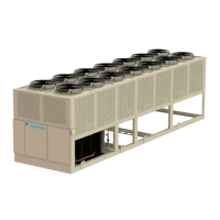
MODEL AGZ CHILLERS 72 www.DaikinApplied.com
CIrCUIT fUnCTIons
Cycle Timers
A minimum time between starts of the compressor and a
minimum time between shutdown and start of the compressor
shall be enforced. The time values are determined by the
Start-start Timer and Stop-start Timer setpoints.
These cycle timers should not be enforced through cycling of
power to the chiller. This means that if power is cycled, the
cycle timers should not be active.
These timers may be cleared via a setting on the controller.
Condenser Fan Control
Condenser fan control should stage fans as needed any time
compressors are running on the circuit. All fans and solenoid
valves will be off when the circuit is in the off and preopen
states. Condenser fan digital outputs will be turned on or
off immediately for condenser stage changes. Condenser
solenoid valve outputs will turn on immediately when a stage
up requires the output to turn on, but will have a delay for
turning off during a stage down. This delay is 20 seconds. If
the circuit shuts off then the condenser solenoid valve outputs
will turn off without a delay.
Condenser Staging
Condenser staging will use up to 5 digital outputs for control of
condenser fans and a digital output for control of a condenser
solenoid valve. When equipped with condenser fan VFDs, the
speed signal(s) also starts and stops the fan that is connected
to the VFD. The total number of fans on shall be adjusted
with changes of one fan at a time. The tables below show the
outputs energized for each stage.
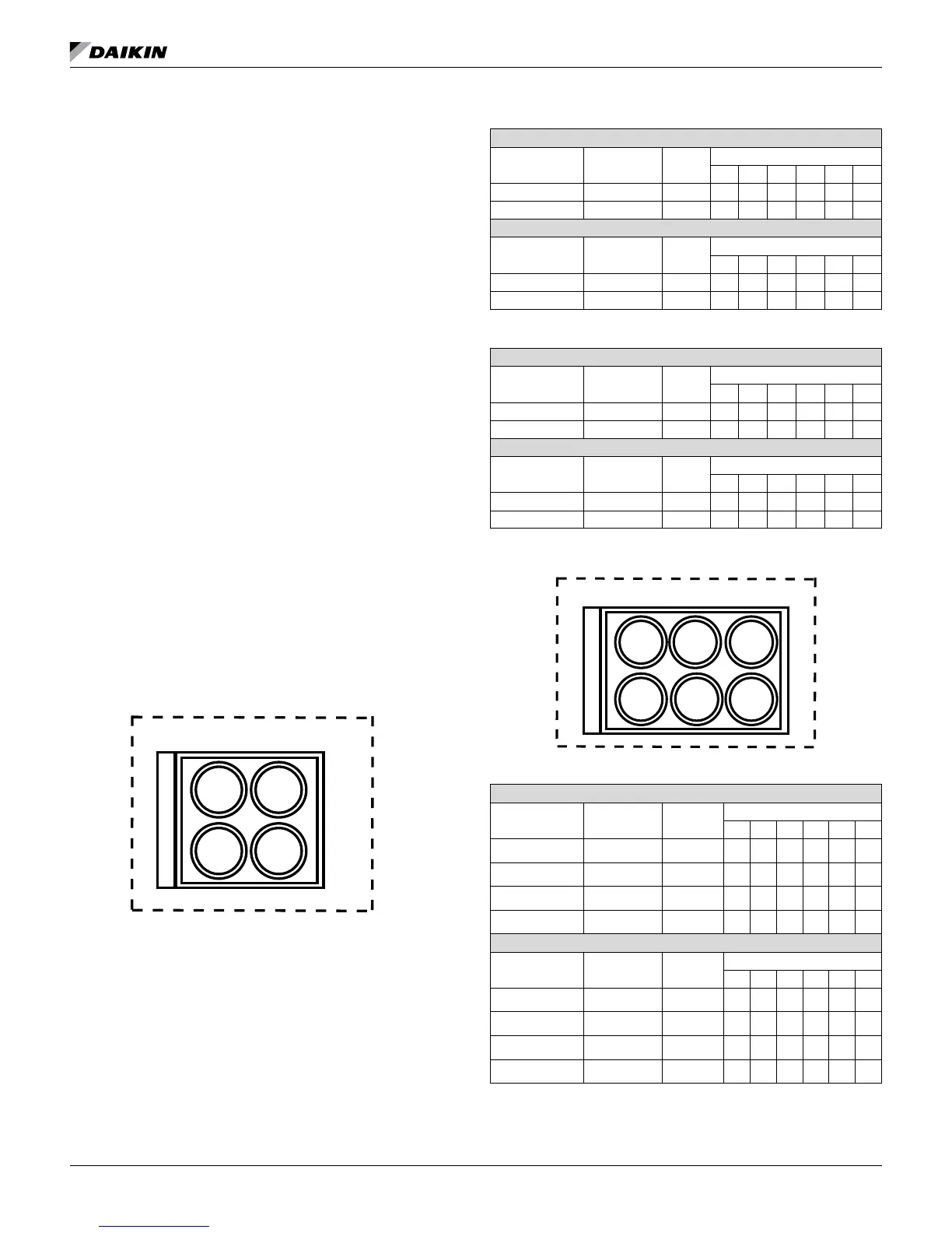
Figure 54: 2 Fans per Circuit - Unit Numbering Schematic
Table 61: 2 Fans per Circuit - Without Fan VFD
Circuit 1
Description Output Fans
Stage
1 2 3 4 5 6
Fan Output 1 UC DO3 Fan 11 On On -- -- -- --
Fan Output 2 UC DO4 Fan 12 On -- -- -- --
Circuit 2
Description Output Fans
Stage
1 2 3 4 5 6
Fan Output 1 UC DO7 Fan 21 On On -- -- -- --
Fan Output 2 UC DO8 Fan 22 On -- -- -- --
Table 62: 2 Fans per Circuit - With 1 Fan VFD per Circuit
Circuit 1
Description Output Fans
Stage
1 2 3 4 5 6
Speed Signal 1 UC X5 Fan 11 On On -- -- -- --
Fan Output 2 UC DO4 Fan 12 On -- -- -- --
Circuit 2
Description Output Fans
Stage
1 2 3 4 5 6
Speed Signal 1 UC X6 Fan 21 On On -- -- -- --
Fan Output 2 UC DO8 Fan 22 On -- -- -- --
Figure 55: 3 Fans per Circuit - Unit Numbering Schematic
Table 63: 3 Fans per Circuit - Without Fan VFD
Circuit 1
Description Output Fans
Stage
1 2 3 4 5 6
Fan Output 1 UC DO3 Fan 11 On On On -- -- --
Fan Output 2 UC DO4 Fan 12 On On -- -- --
Fan Output 3 UC DO5 Fan 13 On
Condenser SV UC X7 SV 11 On
Circuit 2
Description Output Fans
Stage
1 2 3 4 5 6
Fan Output 1 UC DO7 Fan 21 On On On -- -- --
Fan Output 2 UC DO8 Fan 22 On On -- -- --
Fan Output 3 UC DO9 Fan 23 On -- -- --
Condenser SV UC X8 SV 21 On -- -- --
Fan 11
Fan 21
Fan 22
Fan 12
2-Fan Unit Locations and Numbering
Fan 11
Fan 12
Fan 21
Fan 23
Fan 13
Fan 22
3-Fan Unit Locations and Numbering