sTarT-up proCedures
www.DaikinApplied.com 5 IM 1040 • VAV ACTUATOR
Enabling actuators
CAUTION
The controller’s DOs control only 24 Vac loads.
The maximum rating is 12 VA for each DO.
The points that determine actuator run times are:
• MTR 1 TIMING
• MTR 2 TIMING
• MTR 3 TIMING
Your application may not have or use all three points.
1. Use and/or to set run time(s) for actuator(s) used by your
application.
2. For damper rotation angles other than 90°, set DMP
ROT ANG to the appropriate value. The names of these
points vary.
Table 2: Damper Actuator Run Time
Damper Actuator
Setting (seconds)
50Hz 60 Hz
2508021 125 90
2508021P10 125 90
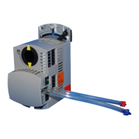
Table 3: Valve Actuator Run Time
Valve Actuator
Setting (seconds)
50 HZ 60 Hz
SSB81U
Floating control fail in-place
160 150
SSC81U
Floating control fail in-place
150 125
SSC81.5U
Floating control fail-safe
125 125
SQS85.53U
Floating control spring return
35 30
Specifying motor setup
CAUTION
If an Autozero Module is used, do not enable MTR3 (valve 2).
NOTICE
When MTR SETUP is changed, all enabled actuators will
calibrate. Wait until each actuator has completed its calibrating
before continuing.
MTRSETUP determines which actuators are controlled by the
application and whether they are direct or reverse acting. Set
MTRSETUP according to Table 4.
Table 4: Motor Enable/Reverse Values for MTR SETUP
(Point 58)
Enabled Enabled and Reversed
Motor 1 (damper)
Motor 2
Not used 1 (default) 3
Enabled 5 7
Enabled and Reversed 13 15
Verifying actuator setup
Command all actuators closed. Verify that they close and
remain closed. If not, adjust the setting for MTRSETUP
according to Table 4.
If any of the actuators still do not close completely, then
the actuators have been installed or set up incorrectly. See
the installation instructions or contact your local Daikin
representative.
Setting the number of heat stages or
valves
CAUTION
For installations using electric heat coils, never set min airow
settings to 0 (zero). Equipment damage can occur if electric
heat is ON without airow.
Depending on the application, HTG STG CNT or VLV CNT (if
present) refers to electric heat stages or valves used (enabled),
some point names may vary.
• Set VLV CNT to the number of valves used for water or
steam valve applications (1 or 2)
• Check the hardware to verify the number of electric heat
stages wired to the controller (1 to 3) and set HTG STG
CNT to the value for electric heat appliactions