Do you have a question about the Daikin BACnet IM 1234-1 and is the answer not in the manual?
Tracks changes and updates to the manual over time.
Lists related documents for further information.
Information regarding the product's warranty coverage.
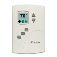
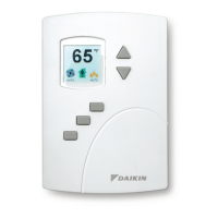
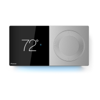
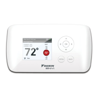
Provides an overview of BACnet thermostats and their applications.
Explains cautionary, warning, danger, and notice symbols.
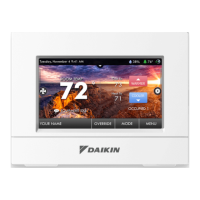
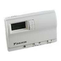
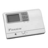
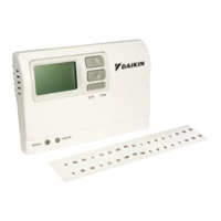
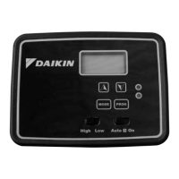
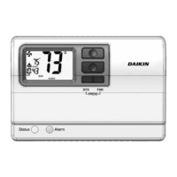
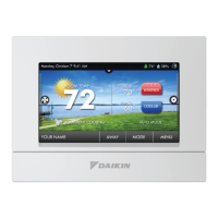
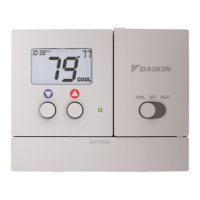
Details the display, buttons, and operator functions.
Describes password protection for users and technicians.
Specifies the screen resolution, size, and backlight.
Overview of pre-programmed and application-specific I/O.
Details types of sensors and input specifications.
Describes output configuration and current ratings.
Specifies terminal block type and wire gauge.
Details network communication standards and speeds.
Provides accuracy specifications for thermistors.
Lists compliance with UL, FCC, and other standards.
Defines operating and shipping temperature and humidity ranges.
Details power supply requirements and case material.
Provides physical dimensions of the thermostat.
Lists product numbers for different unit types.
Explains the coding system for model numbers.
Guidance on optimal placement for accurate temperature sensing.
Steps for wiring and preparing the installation site.
Instructions for wiring various input sensors like temperature and status.
Diagrams and instructions for connecting fan and valve outputs.
Guidelines for wiring the 24 VAC power source.
Procedures for cleaning and general upkeep.
Describes functions accessible to end-users.
Explains navigation and button functions on the interface.
Procedure for setting or entering a four-digit user password.
Steps to adjust heating and cooling temperature setpoints.
Instructions for configuring fan and system modes (Heat, Cool, Auto).
How to temporarily change setpoints when in unoccupied mode.
Method to switch between Celsius and Fahrenheit displays.
Procedure to access advanced technician settings using Password 2.
Configuring operational setpoints and limits using Password 2.
Configuring network properties like Device ID, MAC, and Baud.
Procedure to set the system clock and Daylight Saving Time.
Configuring weekly and holiday schedules for occupancy.
Configuring specific options for fan coil units.
Setting minimum and maximum fan speeds.
Designating the number of fan speeds.
Enabling auxiliary heat functionality.
Configuring specific options for rooftop units.
Configuring economizer settings like damper position and temperature limits.
Setting fan operation for heating calls (Auto/Off).
Configuring specific options for heat pump units.
Configuring the O/B terminal for heating or cooling calls.
Configuring auxiliary heat modes (Comp Lockout, 3rd Stage, None).
Setting minimum OAT for auxiliary heat lockout.
Setting minimum OAT for compressor operation.
Navigating to the advanced options section.
Restoring original settings and selecting metric/English units.
Modifying proportional and integral PID loop parameters.
Managing Password 1 (user) and Password 2 (technician).
Adjusting calibration factors for temperature sensors.
Configuring display behavior (blanking, clock, backlight).
Limiting user access to modes or setpoints via Password 1.
Details on active, occupied, and unoccupied cooling/heating setpoints.
Definitions of active, occupied, and unoccupied setpoints.
Rules regarding setpoint differentials and their impact.
How the thermostat determines and manages occupied/unoccupied states.
Mechanism for automatic mode switching based on temperature.
How internal schedules manage occupancy states.
Explanation of PID loop functionality for temperature control.
How valves operate for heating/cooling in FCU applications.
Method for determining water supply temperature type.
Control of fan operation for FCU units.
User-configurable fan control modes (Auto, On).
Setting fan speeds for variable or three-speed fans.
Configuration of normal/reverse valve action.
Operation of modulating valves for RTU cooling/heating.
Description of staged operation based on demand.
Fan control logic for RTU and HP units.
Economizer operation based on OAT and DAT.
Special functions for heat pump unit operation.
Configuration of the reversing valve output.
Modes for auxiliary/emergency heat operation.
Overview of wiring and application details for fan coil units.
Wiring diagram for FCU with 3-speed fan and modulating valves.
Wiring diagram for FCU with modulating fan and ON/OFF valves.
Wiring diagram for FCU with modulating fan and modulating valves.
Wiring diagram for 2-pipe FCU with 3-speed fan and ON/OFF valves.
Wiring diagram for 2-pipe FCU with 3-speed fan and modulating valve.
Wiring diagram for 2-pipe FCU with modulating fan and ON/OFF valve.
Wiring diagram for 2-pipe FCU with modulating fan and modulating valve.
Wiring diagram for RTU with 2-stage heat and DX cooling.
Wiring diagram for RTU with 2-stage heat, DX cooling, and economizer.
Wiring diagram for RTU with 2-stage heat, chilled water cooling, and economizer.
Wiring diagram for RTU with modulating cooling/heating and economizer.
Wiring diagram for HP unit with 3 heat and 2 cool stages.
Wiring diagram for HP unit with 3 heat, 2 cool, and economizer.
Procedure for connecting the thermostat to a BACnet MS/TP network.
| Brand | Daikin |
|---|---|
| Model | BACnet IM 1234-1 |
| Category | Thermostat |
| Language | English |