Do you have a question about the Daikin 668811201 and is the answer not in the manual?
Diagrams for heating-only systems with single transformer.
Diagrams for heating/cooling systems with single transformer.
Diagrams for cooling-only systems with single transformer.
Detailed settings for thermostat configuration.
Select Fahrenheit or Celsius for temperature display.
Set the temperature difference for system activation.
Set minimum difference between heat and cool setpoints.
Configure heat pump, non-heat pump, and compressor stages.
Set temperature adjustment limits during keypad lockout.
Control the maximum allowable heat set temperature.
Control the minimum allowable cool set temperature.
Calibrate displayed room temperature to actual temperature.
Set the maximum number of system cycles per hour.
Select sensor source: on-board, remote, or average.
Set fan purge time for cooling operation.
Configure the status indicator light behavior.
Thermostat is inactive; no heating or cooling devices operate.
Thermostat controls the heating system.
Thermostat controls the cooling system.
Thermostat automatically switches between heating and cooling.
Verify heating system responds correctly to setpoint changes.
Verify cooling system responds correctly to setpoint changes.
Verify the indoor fan operates correctly.
Lists common issues and their solutions.
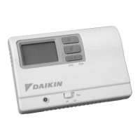
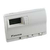
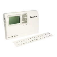
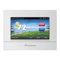
This document describes the Daikin 668811101 Non-Programmable Electronic Thermostat, a versatile control unit designed for various heating and cooling systems. It supports 1 Heat/1 Cool, Auto Changeover, and features fan speed control, making it suitable for both residential and light commercial applications.
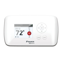
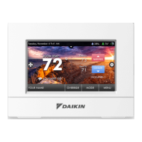
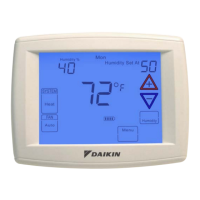
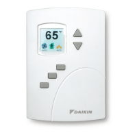
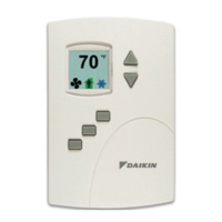
The thermostat's primary function is to regulate room temperature by controlling heating and cooling equipment. It operates on 24 VAC and is compatible with single-stage heat/cool systems, single-stage heat pump systems, gas, oil, or electric heat systems. Users can select between Fahrenheit or Celsius temperature scales. The auto changeover feature allows the thermostat to automatically switch between heating and cooling modes as needed to maintain a desired temperature range. A status indicator light provides visual feedback on the system's operation.
The thermostat boasts a large display with a backlight for easy readability, even in low-light conditions. Its SimpleSet™ Field Programming feature simplifies setup, allowing installers to configure one "master" thermostat and then quickly transfer those settings to multiple "target" thermostats using a dedicated transfer cable. This is particularly useful for installations involving numerous units, such as in new construction or multi-zone systems.
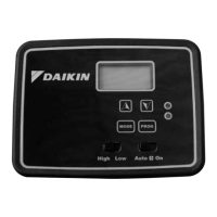
The device offers four operating modes: OFF, Heat, Cool, and Cool & Heat (Auto Changeover). In OFF mode, the thermostat will not activate heating or cooling devices, though the indoor fan can still be manually operated. In Heat mode, it controls the heating system, displaying a flame icon when active. For heat pumps, a four-minute delay is incorporated before the compressor restarts to protect the equipment. Similarly, in Cool mode, it manages the cooling system, showing a snowflake icon when active, also with a four-minute compressor restart delay for heat pumps. The Cool & Heat mode provides automatic changeover between heating and cooling to maintain comfort.
A key user-friendly feature is the ability to adjust the temperature differential, which sets the number of degrees between the setpoint temperature and the "turn on" temperature, allowing for fine-tuning of system cycling. The deadband setting in Autochangeover mode defines the minimum temperature difference between heat and cool setpoints.
The thermostat supports remote or outdoor sensors, which can be installed to provide more accurate temperature readings or to monitor outdoor conditions. The display can show the remote or outdoor temperature by simultaneously pressing the Down and SYS buttons.
For security and to prevent unauthorized adjustments, the thermostat includes a lockout feature. This allows installers to limit temperature adjustments and prevent changes to the operating mode. The lockout level can be configured, specifying the number of degrees the set temperature can be changed during keypad lockout.
The manual emphasizes safety during installation and maintenance, instructing users to always turn off power at the main supply before working with the thermostat. It provides clear instructions for removing an existing thermostat and installing the new Daikin unit, including proper wiring procedures and mounting guidelines.
Troubleshooting tips are included to help diagnose common issues, such as a blank display, inoperative buttons, or incorrect temperature readings. For instance, if the display is blank, users are advised to check for 24 VAC at the thermostat. If all buttons are inoperative, verifying 24 VAC is present is recommended, as the unit locks out without power. If the thermostat cycles too frequently, adjusting the temperature differential is suggested. For inaccurate room temperature, calibration or checking remote sensor connections (if used) are recommended. A reset button is available to reset time and day settings without altering configuration settings.
The SimpleSet™ feature, while primarily for installation, also aids in maintenance by ensuring consistent settings across multiple units, simplifying future troubleshooting or adjustments. The clear wiring diagrams and step-by-step configuration mode settings further contribute to ease of maintenance and setup.
| Model Number | 668811201 |
|---|---|
| Brand | Daikin |
| Display | LCD |
| Power Supply | 24VAC |
| Communication | Wired |
| Compatibility | Daikin systems |
| Temperature Setting Resolution | 1°F or 0.5°C |