Specifications
Electrical rating: • 24VAC(18-30VAC)
• 1ampmaximumperterminal
• 3ampmaximumtotalload
Temperature control range: 55°Fto90°F(13°Cto32°C)Accuracy:±1°F(±0.5°C)
System congurations:2-stageheat,2-stagecool
Timing:Anti-shortCycle:4minutes(bypassanti-shortcycledelaybyreturningtoOFFmodefor5seconds)
BacklightOperation:10seconds
Terminations:A,L,S1,S2,R,C,W1,Y1,W2,Y2,G,O
Package Contents/Tools Required
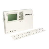
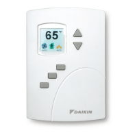
Package includes:910121746thermostatonbase,thermostatcover,wiringlabels,screwsandwallanchors,
Installation,OperationandApplicationGuide
Tools required for installation:Drillwith3/16”bit,hammer,screwdriver
Important Safety Information
WARNING!
:
Always turn off power at the main power supply before installing, cleaning, or removing
thermostat.
• Thisthermostatisfor24VACapplicationsonly;donotuseonvoltagesover30VAC
• Allwiringmustconformtolocalandnationalelectricalandbuildingcodes
• Donotuseairconditioningwhentheoutdoortemperatureisbelow50degrees;thiscandamageyourA/Csystem
andcausepersonalinjuries
• Usethisthermostatonlyasdescribedinthismanual
Icon Descriptions
Coolingoperationicon
Fanoperationicon
Heatingoperationicon
Roomtemperature
offsetactivated
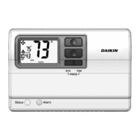
Parts Diagram
Conguration
switch
Resetswitch
Right(fan)button
Downbutton
Upbutton
S1 S2 R C GY1 W2 Y2
RESET CONFIG
To Remove Existing Thermostat
ELECTRICAL SHOCK HAZARD
– Turn off power at the main service panel by removing the fuse
or switching the appropriate circuit breaker to the OFF position before removing the existing
thermostat.
1. Turnoffpowertotheheatingandcoolingsystembyremovingthefuseorswitchingtheappropriatecircuit
breakeroff.
2. Removecoverofoldthermostat.Thisshouldexposethewires.
3. Labeltheexistingwireswiththeenclosedwirelabelsbeforeremovingwires.
4. Afterlabelingwires,removewiresfromwireterminals.
5. Removeexistingthermostatbasefromwall.
6. Refertothefollowingsectionforinstructionsonhowtoinstallthisthermostat.
To Install Thermostat
ELECTRICAL SHOCK HAZARD
– Turn off power at the main service panel by removing the fuse
or switching the appropriate circuit breaker to the OFF position before removing the existing
thermostat.
IMPORTANT: Thermostat installation must conform to local and national building and electrical codes and
ordinances.
Note:Mount the thermostat about ve feet above the oor. Do not mount the thermostat on an outside wall, in
direct sunlight, behind a door, or in an area affected by a vent or duct.
1.Turnoffpowertotheheatingandcoolingsystembyremovingthefuseorswitchingtheappropriatecircuitbreaker
off.
2.Toremovecover,pullgentlyattheseamatthetop.
3.Putthermostatbaseagainstthewallwhereyouplantomountit(Besurewireswillfeedthroughthewireopening
inthebaseofthethermostat).
4.Marktheplacementofthemountingholes.
5.Setthermostatbaseandcoverawayfromworkingarea.
6.Usinga3/16”drillbit,drillholesintheplacesyouhavemarkedformounting.
7.Useahammertotapsuppliedanchorsinmountingholes.
TerminalsS1andS2canbeusedforanindoorremotesensor.
Theindoorremotesensorisusedtoreadtheindoortemperature
inadifferentlocation.Thisisbenecialwhenthethermostatisnot
mountedintheideallocation.TheremotesensorP/Nis910116773.
1. Removecoverfromremotesensorhousing.
2. Selectanappropriatelocationformountingtheremotesensor.
3. Mountremotesensorunitusinghardwareprovided.
4. Installtwostrandshieldedwirebetweenremotesensorand
thermostat.Shieldedwireisrecommended.
Do notrunremotesensorwireinconduitwithotherwires.
• Wire 1shouldrunbetweentheS1terminalonthethermostat
andtheS1terminalontheremotesensor
• Wire 2shouldrunbetweentheS2terminalonthethermostat
andtheS2terminalontheremotesensor
• ConnecttheshieldingofthewiretotheS2terminalonthethermostat
5. Congurethethermostattooperatewiththeremoteindoorsensor(seeCongurationModesetting9).
Remote Sensor Installation (Optional)
Note: Remote or outdoor sensor reading can be
displayed by simultaneously pressing the
Down and SYS buttons.
Remote Sensor:
(Contact Daikin for optional remote sensor.)
8.Alignthermostatbasewithmountingholesandfeedthecontrolwiresthroughslitinthermalintrusionbarrierand
intowireopening.
9.Usesuppliedscrewstomountthermostatbasetowall.
10.Insertstripped,labeledwiresinmatchingwireterminals.
CAUTION!
:Be sure exposed portion of wires does not touch other wires.
11. Gentlytugwiretobesureofproperconnection.Doublecheckthateachwireisconnectedtotheproper
terminal.
12.Turnonpowertothesystematthemainservicepanel.
13.Congurethermostattomatchthetypeofsystemyouhave.
14.Replacecoveronthermostatbysnappingitinplace.
15.Testthermostatoperationasdescribedin“TestingtheThermostat”.
1
ST
Cool 2
ND
Cool 1
ST
Heat 2
ND
Heat
Heat/Cool Y1 YI,Y2 W1 W1,W2
The910121746thermostatiscongurableforallsystems.Thecongurationdirectlyaffectstheoutputs.
Usetheoutputcharttocorrectlycongureandwirethethermostattoyoursystem.
910121746 Output Chart
Configuration Mode
OFF
1. Verifythe910121746isintheOFFmode.
PresstheSYS(left)buttonuntiloffmodedisplays.
2. Removethecoverofthethermostatbygentlypullingnearoneofthecornersat
thetopofthethermostat.
Toexitcongurationmode,presstheCONFIGswitchfor1second.
Presstheupordownbuttontochangesettingswithineachscreen.
Downbutton
Upbutton
Presstherightbuttontoadvancetothenextscreen.
Note:Pressing the
left
button will return you to the previous screen.
Left
button
Right
button
Thecongurationmodeisusedtosetthe910121746tomatchyourheating/coolingsystem.Tocongurethe
910121746,performthefollowingsteps:
3. PresstheCONFIGbuttonfor1secondwhilethe910121746isinOFF mode.
CONFIG
S1 S2 R C W
O/B
GY1 W2 W3Y2
RESET CONFIG
FP
Wiring Diagrams
L
S1
S2
R
C
W1
Y1
W2
Y2
G
A
O
O
G
Y1
Y2
W1
W2
A
R
C
4
3
2
1
5
O
G
Y1
Y2
W1
W2
A
R
C
ICM
Thermostat
Terminal
TB2
TB1
ICM
Thermostat
Terminal