EasyManua.ls Logo

Daikin 910121748 - User Manual

Daikin 910121748
2 pages
Print Icon
To Next Page IconTo Next Page
Loading...
Specifications
Electrical rating: • 24VAC(18-30VAC)
• 1ampmaximumperterminal
• 3ampmaximumtotalload
Temperature control range: 55°Fto90°F(13°Cto32°C)Accuracy:±1°F(±0.5°C)
System congurations:2-stageheat,2-stagecool
Timing:Anti-shortCycle:4minutes(bypassanti-shortcycledelaybyreturningtoOFFmodefor5seconds)
BacklightOperation:10seconds
Terminations:A,L,S1,S2,R,C,W1,Y1,W2,Y2,G,O
Package Contents/Tools Required
Package includes:910121748thermostatonbase,thermostatcover,wiringlabels,screwsandwallanchors,
Installation,OperationandApplicationGuide
Tools required for installation:Drillwith3/16”bit,hammer,screwdriver
Important Safety Information
WARNING!
:
Always turn off power at the main power supply before installing, cleaning, or removing
thermostat.
• Thisthermostatisfor24VACapplicationsonly;donotuseonvoltagesover30VAC
• Allwiringmustconformtolocalandnationalelectricalandbuildingcodes
• Donotuseairconditioningwhentheoutdoortemperatureisbelow50degrees;thiscandamageyourA/Csystem
andcausepersonalinjuries
• Usethisthermostatonlyasdescribedinthismanual
To Remove Existing Thermostat
ELECTRICAL SHOCK HAZARD
– Turn off power at the main service panel by removing the fuse
or switching the appropriate circuit breaker to the OFF position before removing the existing
thermostat.
1. Turnoffpowertotheheatingandcoolingsystembyremovingthefuseorswitchingtheappropriatecircuit
breakeroff.
2. Removecoverofoldthermostat.Thisshouldexposethewires.
3. Labeltheexistingwireswiththeenclosedwirelabelsbeforeremovingwires.
4. Afterlabelingwires,removewiresfromwireterminals.
5. Removeexistingthermostatbasefromwall.
6. Refertothefollowingsectionforinstructionsonhowtoinstallthisthermostat.
To Install Thermostat
ELECTRICAL SHOCK HAZARD
– Turn off power at the main service panel by removing the fuse
or switching the appropriate circuit breaker to the OFF position before removing the existing
thermostat.
IMPORTANT: Thermostat installation must conform to local and national building and electrical codes and
ordinances.
Note:Mount the thermostat about ve feet above the oor. Do not mount the thermostat on an outside wall, in
direct sunlight, behind a door, or in an area affected by a vent or duct.
1.Turnoffpowertotheheatingandcoolingsystembyremovingthefuseorswitchingtheappropriatecircuitbreaker
off.
2.Toremovecover,pullgentlyattheseamatthetop.
3.Putthermostatbaseagainstthewallwhereyouplantomountit(Besurewireswillfeedthroughthewireopening
inthebaseofthethermostat).
4.Marktheplacementofthemountingholes.
5.Setthermostatbaseandcoverawayfromworkingarea.
6.Usinga3/16”drillbit,drillholesintheplacesyouhavemarkedformounting.
7.Useahammertotapsuppliedanchorsinmountingholes.
8.Alignthermostatbasewithmountingholesandfeedthecontrolwiresthroughslitinthermalintrusionbarrierand
intowireopening.
9.Usesuppliedscrewstomountthermostatbasetowall.
10.Insertstripped,labeledwiresinmatchingwireterminals.
CAUTION!
:Be sure exposed portion of wires does not touch other wires.
11.Gentlytugwiretobesureofproperconnection.Doublecheckthateachwireisconnectedtotheproper
terminal.
12.Turnonpowertothesystematthemainservicepanel.
13.Congurethermostattomatchthetypeofsystemyouhave.
14.Replacecoveronthermostatbysnappingitinplace.
15.Testthermostatoperationasdescribedin“TestingtheThermostat”.
Parts Diagram
Icon Descriptions
Coolingoperationicon
Fanoperationicon
Heatingoperationicon
Roomtemperature
offsetactivated
1
ST
Cool 2
ND
Cool 1
ST
Heat 2
ND
Heat
Heat/Cool Y1 YI,Y2 W1 W1,W2
The910121748thermostatiscongurableforallsystems.Thecongurationdirectlyaffectstheoutputs.
Usetheoutputcharttocorrectlycongureandwirethethermostattoyoursystem.
910121748 Output Chart
Configuration Mode
OFF
PM
1. Verifythe910121748isintheOFFmode.
PresstheSYS(left)buttonuntiloffmodedisplays.
2. Removethecoverofthethermostatbygentlypullingnearoneofthecornersat
thetopofthethermostat.
3. PresstheCONFIGbuttonfor1secondwhilethe910121748isinOFF mode.
Toexitcongurationmode,presstheCONFIGswitchfor1second.
Presstheupordownbuttontochangesettingswithineachscreen.
Downbutton
Upbutton
Presstherightbuttontoadvancetothenextscreen.
Note:Pressing the
left
button will return you to the previous screen.
Left
button
Right
button
Thecongurationmodeisusedtosetthe910121748tomatchyourheating/coolingsystem.Tocongurethe
910121748,performthefollowingsteps:
CONFIG
S1 S2 R C W
O/B
GY1W2 W3Y2
RESET CONFIG
FP
6. Maximum Heat Setpoint(55°Fto90°F)(13°Cto32°C)
Adjusttocontrolthemaximumheatsettemperatureallowed.
Presstheupordownbuttontoselect.
Presstherightbuttontoadvancetothenextscreen.
7. Minimum Cool Setpoint(55°Fto90°F)(13°Cto32°C)
Adjusttocontroltheminimumcoolsettemperatureallowed.
Presstheupordownbuttontoselect.
Presstherightbuttontoadvancetothenextscreen.
9. Temperature Sensor(1-4)
1.Onlyon-boardsensordeterminesroomtemperature.
2.Onlyremotesensordeterminesroomtemperature.
3.Averagetemperatureofon-boardandremotesensor.
4.Onlyon-boardsensorwillbeuseduntilNITEperiod,andthenonlyremote
sensorisused.
Note:If there is no remote sensor, option 1 must be selected.
Presstheupordownbuttontoselect.
Pressthecongurationbuttonfortwosecondstoexitconguration.
8. Room Temperature Offset(+9°Fto-9°F)(+4.5°Cto-4.5°C)
Adjusttocalibratedisplayedroomtemperaturetomatchactualroomtemperature.
Note:When not set to 0, will display.
Presstheupordownbuttontoselect.
Presstherightbuttontoadvancetothenextscreen.
Configuration Mode Settings
ThesetupscreensforCongurationModeareasfollows:
1. Temperature Scale (ForC)
ChooseFahrenheitorCelsius.
Presstheupordownbuttontoselect.
Pressthe
right
buttontoadvancetothenextscreen.
2. 1
st
Stage Temperature Differential(1°Fto5°F)(0.5°Cto2.5°C)
Setthenumberofdegreesbetweenyour“setpoint”temperatureandyour“turnon”
temperature.
Presstheupordownbuttontosetdifferentialvalue.
Presstheright buttontoadvancetothenextscreen.
4. Staged Off Outputs
Selectwhethertheoutputsforheatingandcoolingarestagedoffindependentlyor
aresatisedsimultaneously.
1=outputsstagedoffindependently
0=outputsoffsimultaneously
Presstheupordownbuttontoset.
Presstheright buttontoadvancetothenextscreen.
5. Minimum Deadband(1°Fto9°F)(1°Cto5°C)
SettheminimumseparationbetweenheatsetpointandcoolsetpointinAuto
ChangeoverMode.
Presstheupordownbuttontosetdeadbandvalue.
Presstheright buttontoadvancetothenextscreen.
3. 2
nd
Stage Temperature Differential(1°Fto5°F)(0.5°Cto2.5°C)
Setthenumberofdegreesbetweenwhenstage1turnsonandwhenstage2turnson.
Presstheupordownbuttontosetdifferentialvalue.
Presstheright buttontoadvancetothenextscreen.
Wiring Diagrams
Conguration
switch
Resetswitch
Right(fan)button
Downbutton
Upbutton
S1 S2 R C GY1 W2 Y2
RESET CONFIG
Mode of Operation
The910121748isaprogrammable,manualorautochangeover,2-stageheat,2-stagecoolthermostat.Anoutdoor
sensorcanbeusedtomonitortheoutdoortemperature.
Thethermostatactivatestheheatingappliancewhentheroomtemperatureisbelowthesetheattemperature(by
thedifferentialtemperature).The910121748willstopoutputtingwhenthecallforheathasbeensatised.
Whentheroomtemperatureisgreaterthanthesetcooltemperature(bythedifferentialtemperature),thecooling
deviceisactivated.The910121748willstopoutputtingwhenthecallforcoolingissatised.
The910121748hasvepossibleoperatingmodes:OFF,Heat,Cool,Heat & Cool,andProgrammode.Inoff
mode,thethermostatwillnotturnonheatingorcoolingdevices.Themanualfancanbeturnedoninalloperating
modesusingthefanbutton.Inheatmode,thethermostatcontrolstheheatingsystem.Inthecoolmode,the
thermostatcontrolsthecoolingsystem.Inheat&coolmode,thethermostatcontrolsboththeheatingandcooling
systems.Inprogrammode,thethermostatwillautomaticallybecontrolledbythesetprogram.Programmodecan
functionwithheatmode,coolmode,orheat&coolmode.Theclockdisplayalternateswiththesettemperature
displayforheat&coolmode.
Theprogramschedulecanbeoverriddenbychangingthesettemperature(upordownbutton).Thisputsthe
910121748thermostatintoa2-hourtemporaryhold.After2hours,itwillautomaticallyreturntotheprogram
schedule.
TheprogrammablefanfeaturecanbeusedtorecirculateairwhileinProgrammode.Itisactivatedduringthe
programschedulesetup.
PressingtheUPandDOWNbuttonssimultaneouslyfor2secondsthenreleasingthemcausesthethermostatto
outputfromthe“O”terminalfor5seconds.“Or”willshowonthedisplay.Thiswillresultintheunitgoingintoanight
set-backoverride.
PressingtheUPandDOWNbuttonssimultaneouslyfor5secondscausesthethermostattooutputfromthe“O”
terminalfor10seconds.“rS”willshowonthedisplay.Thiswillresultintheunitbeingreset.
Button Functions
UP–Usedtoincreasethetime,settemperaturesandtoadjustconguration
settings.
DOWN–Usedtodecreasethetime,settemperaturesandtoadjust
congurationsettings.
SYS (left)– UsedtochangefromOFF,HEAT,COOLandAUTOchangeover
modes
FAN (right)–Usedtoturnonandofftheindoorfan.
PROG (SYS and FAN)–Usedtochangefromprogramoperationtomanualoperation.
DOWN and SYS–Pressedsimultaneouslytodisplayoutdoorremotetemperatureifremotesensoris
connected.
UP and DOWN– Usedtooverridenightsetbackorresettheunit.
PROG
FAN
(right)
Down
button
Up
button
SYStem
(left)
TerminalsS1andS2canbeusedforanindoorremotesensor.
Theindoorremotesensorisusedtoreadtheindoortemperature
inadifferentlocation.Thisisbenecialwhenthethermostatisnot
mountedintheideallocation.TheremotesensorP/Nis910116773.
1. Removecoverfromremotesensorhousing.
2. Selectanappropriatelocationformountingtheremotesensor.
3. Mountremotesensorunitusinghardwareprovided.
4. Installtwostrandshieldedwirebetweenremotesensorand
thermostat.Shieldedwireisrecommended.
Do notrunremotesensorwireinconduitwithotherwires.
• Wire 1shouldrunbetweentheS1terminalonthethermostat
andtheS1terminalontheremotesensor
• Wire 2shouldrunbetweentheS2terminalonthethermostatandtheS2terminalontheremotesensor
• ConnecttheshieldingofthewiretotheS2terminalonthethermostat
5. Congurethethermostattooperatewiththeremoteindoorsensor(seeCongurationModesetting9).
Remote Sensor Installation (Optional)
Note: Remote or outdoor sensor reading can be
displayed by simultaneously pressing the
Down and SYS buttons.
Remote Sensor:
(Contact Daikin for optional remote sensor.)
Terminal Designator Descriptions
R–24VAChot
C–24VACcommon
W1–1ststageheat
Y1–1ststagecool
W2–2ndstageheat
Y2–2ndstagecool
G – Fan
A – Alarminput
L – Statusinput
O – Override/reset
L
S1
S2
R
C
W1
Y1
W2
Y2
G
A
O
O
G
Y1
Y2
W1
W2
A
R
C
4
3
2
1
5
O
G
Y1
Y2
W1
W2
A
R
C
ICM
Thermostat
Terminal
TB2
TB1
ICM
Thermostat
Terminal
WSHP Main Control Board
Terminals TB1 and TB2
Daikin P/N (910121748)
Installation, Operation & Application Guide
• 7-Day, 5-2-Day or 5-1-1-Day
Programmable
• Configurable
• 2-Stage Heat/2-Stage Cool Systems
• Large Display With Backlight
• Selectable Fahrenheit or Celsius
• Status Indicator Light
• Relay Outputs
(minimum voltage drop in thermostat)
• Remote Sensor Compatible
Version B: 10-15-13
2 Heat/2 Cool, 7-Day Programmable, Auto Changeover, Hardwired
Programmable Electronic Thermostat
Question and Answer IconNeed help?

Do you have a question about the Daikin 910121748 and is the answer not in the manual?

Summary

Thermostat Installation

To Remove Existing Thermostat

Steps to safely disconnect and remove the old thermostat unit before installation.

To Install Thermostat

Instructions for mounting the new thermostat base and connecting wires to terminals.

Remote Sensor Installation

Guide for connecting an optional remote sensor for temperature readings in other locations.

Thermostat Operation and Configuration

Wiring Diagrams

Visual representation of terminal connections for various system types and their descriptions.

Configuration Mode

Process for setting thermostat parameters to match system requirements and preferences.

Mode of Operation

Explanation of the thermostat's operating modes: OFF, Heat, Cool, Heat & Cool, and Program.

Button Functions

Description of the purpose and operation of each thermostat button on the control panel.

Operating Modes

OFF Mode

Description of the OFF mode where neither heating nor cooling devices are activated.

Heat Mode

Explanation of how the thermostat controls the heating system operation.

Cool Mode

Explanation of how the thermostat controls the cooling system operation.

Cool and Heat Mode (Auto Changeover)

How the thermostat automatically controls both heating and cooling systems.

Program Mode

How the thermostat operates automatically based on the programmed schedule.

Programming and Testing

Setting the Time and Day of the Week

Procedure for setting the current time and day for accurate program scheduling.

Factory Preprogramming

Overview of the default programmed schedule provided by the manufacturer.

Personal Program Schedule

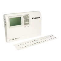
Template to record custom programmed heating and cooling schedules.

Testing the Thermostat

Steps for verifying proper operation of heating, cooling, and fan functions.

Troubleshooting

Troubleshooting

Common symptoms and their corresponding remedies for thermostat issues.

Overview

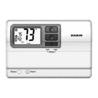
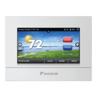
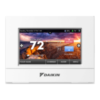
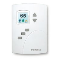
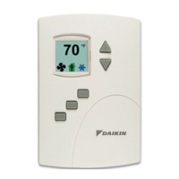
The Daikin 910121748 is a programmable electronic thermostat designed for residential and light commercial HVAC systems. It supports 2-stage heating and 2-stage cooling systems, offering flexible control over indoor climate. The thermostat features a large display with a backlight, making it easy to read in various lighting conditions. Users can choose to display temperatures in either Fahrenheit or Celsius, catering to different regional preferences. A status indicator light provides quick visual feedback on the system's current operation. The device utilizes relay outputs, ensuring reliable communication with HVAC equipment while minimizing voltage drop within the thermostat itself. For enhanced temperature sensing accuracy or placement flexibility, the thermostat is compatible with remote sensors.

Function Description

The thermostat operates in several modes: OFF, Heat, Cool, Heat & Cool (Auto Changeover), and Program mode. In OFF mode, the thermostat disables both heating and cooling functions. The indoor fan can still be manually activated in any operating mode by pressing the FAN button. In Heat mode, the thermostat exclusively controls the heating system, activating the heating appliance when the room temperature falls below the set heat temperature by a user-defined differential. The flame icon appears on the display when heating is active. Conversely, in Cool mode, the thermostat manages only the cooling system, engaging the cooling device when the room temperature exceeds the set cool temperature by its differential. The snowflake icon indicates active cooling.

The Heat & Cool (Auto Changeover) mode provides automatic switching between heating and cooling as needed, maintaining a comfortable temperature range. In this mode, the display alternates between the current time and the set temperature every 10 seconds. The Program mode allows the thermostat to follow a pre-set schedule, automatically adjusting temperatures throughout the day. This mode can be combined with Heat, Cool, or Heat & Cool functionalities.

The thermostat supports 7-day programming, with options for 5-2-day or 5-1-1-day schedules, allowing users to customize temperature settings for different days of the week. Each day can have four distinct periods: MORN (morning), DAY, EVE (evening), and NITE (night). For each period, users can define a start time, a heat set temperature, a cool set temperature, and a programmable fan option (either off or continuously on). The programmable fan feature is active only in Program mode and helps recirculate air according to the schedule.

A temporary hold feature allows users to override the program schedule by manually adjusting the set temperature. This hold lasts for two hours, after which the thermostat automatically reverts to the programmed schedule. To manually return to the program schedule before the two-hour hold expires, the PROG button can be pressed twice.

The thermostat also includes an anti-short cycle delay of four minutes to protect HVAC equipment from rapid cycling. This delay can be bypassed by returning the thermostat to OFF mode for five seconds. A night set-back override can be activated by simultaneously pressing the UP and DOWN buttons for two seconds, causing the thermostat to output from the "O" terminal for five seconds and displaying "Or". Pressing these buttons simultaneously for five seconds will reset the unit, outputting from the "O" terminal for ten seconds and displaying "rS".

Usage Features

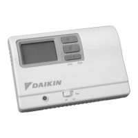
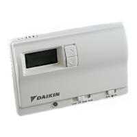
The user interface is designed for straightforward operation. The large display clearly shows the room temperature and current settings. Navigation is managed through a set of intuitive buttons: UP, DOWN, SYS (left), and FAN (right). The UP and DOWN buttons are used to adjust time, set temperatures, and modify configuration settings. The SYS (left) button cycles through the operating modes (OFF, HEAT, COOL, AUTO changeover). The FAN (right) button controls the indoor fan, turning it on or off. The PROG function, which switches between program operation and manual operation, is accessed by simultaneously pressing the SYS and FAN buttons.

For remote temperature monitoring, the thermostat can display the outdoor remote temperature if a compatible sensor is connected, by simultaneously pressing the DOWN and SYS buttons. The UP and DOWN buttons also provide a quick way to override the night set-back or reset the unit.

Configuration mode allows users to customize various thermostat settings to match their specific HVAC system and preferences. These settings include:

  • Temperature Scale: Choosing between Fahrenheit or Celsius.
  • 1st Stage Temperature Differential: Setting the temperature difference between the setpoint and when the first stage of heating or cooling turns on (e.g., 1°F to 5°F).
  • 2nd Stage Temperature Differential: Setting the temperature difference between when the first stage turns on and when the second stage turns on (e.g., 1°F to 5°F).
  • Staged Off Outputs: Deciding whether heating and cooling outputs are staged off independently or simultaneously.
  • Minimum Deadband: Setting the minimum separation between the heat setpoint and cool setpoint in Auto Changeover Mode (e.g., 1°F to 9°F).
  • Maximum Heat Setpoint: Adjusting the highest allowed heat set temperature.
  • Minimum Cool Setpoint: Adjusting the lowest allowed cool set temperature.
  • Room Temperature Offset: Calibrating the displayed room temperature to match the actual room temperature (e.g., +9°F to -9°F).
  • Temperature Sensor: Selecting which sensor determines the room temperature (on-board, remote, average of both, or on-board until NITE period then remote).

The backlight illuminates the display for 10 seconds after a button press, improving visibility in low-light conditions.

Maintenance Features

The thermostat includes troubleshooting guidance to help users diagnose and resolve common issues. This includes remedies for problems such as no display, inoperative buttons, incorrect program schedule activation, frequent cycling, fan issues, incorrect room temperature readings, and alarm conditions. For instance, if there's no display, users are advised to check for 24 VAC at the thermostat. If all buttons are inoperative, checking for 24 VAC and noting that the unit locks out without power is recommended. Incorrect program activation often points to issues with the time (AM/PM) setting.

The thermostat features a reset switch. Pressing the reset switch will reset the time and day, but configuration and program settings remain unchanged, allowing for a quick refresh without losing personalized settings. If an alarm light is on, it indicates the unit is in an alarm lockout condition, which can often be resolved by pressing the reset button. The manual also provides instructions for testing the thermostat's heating, cooling, and fan functions after installation or configuration to ensure proper operation. This involves adjusting set temperatures to trigger the system and observing the response.

Daikin 910121748 Specifications

General IconGeneral
Model Number910121748
CategoryThermostat
CompatibilityDaikin HVAC systems
DisplayLCD
ProgrammableYes

Related product manuals