Package Contents/Tools Required
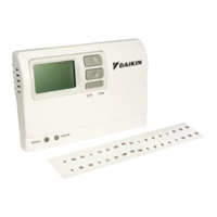
Package includes: Thermostatonbase,thermostatcover,wiringlabels,screwsandwallanchors,
Installation,OperationandApplicationGuide
Tools required for installation:Drillwith3/16”bit,hammer,screwdriver
Important Safety Information
WARNING!
:Always turn off power at the main power supply before installing, cleaning, or
removing thermostat.
• Thisthermostatisfor24VAC/VDCapplicationsonly;donotuseonvoltagesover30VAC/VDC
• Donotshortacrossterminalsofsystemcontroltotestoperation;thiswilldamageyourthermostat
andvoidyourwarranty
• Allwiringmustconformtolocalandnationalelectricalandbuildingcodes
• Usethisthermostatonlyasdescribedinthismanual
Specifications
Electrical rating: •24VAC/VDC(18-30VAC/VDC)
•1ampmaximumperterminal
•4ampmaximumtotalload
Temperature control range: 45°Fto90°F(7°Cto32°C)Accuracy:±1°F(±0.5°C)
System congurations:2-stageheat,2-stagecool
Timing:
BacklightOperation:
13secondsaftermodechangeorbuttonpress
Terminations:-C,+R,W1,Y1,W2,Y2,G,O,S1,S2
To Remove Existing Thermostat
ELECTRICAL SHOCK HAZARD –Turn off power at the main service panel by removing
the fuse or switching the appropriate circuit breaker to the OFF position before removing the
existing thermostat.
1. Turnoffpowertotheheatingandcoolingsystembyremovingthefuseorswitchingtheappropriate
circuitbreakeroff.
2. Removecoverofoldthermostat.Thisshouldexposethewires.
3. Labeltheexistingwireswiththeenclosedwirelabelsbeforeremovingwires.
4. Afterlabelingwires,removewiresfromwireterminals.
5. Removeexistingthermostatbasefromwall.
6. Refertothefollowingsectionforinstructionsonhowtoinstallthisthermostat.
To Install Thermostat
ELECTRICAL SHOCK HAZARD –Turn off power at the main service panel by removing
the fuse or switching the appropriate circuit breaker to the OFF position before removing the
existing thermostat.
IMPORTANT:Thermostat installation must conform to local and national building and
electrical codes and ordinances.
Note:
Mountthethermostataboutvefeetabovetheoor.Donotmountthethermostat
onanoutsidewall,indirectsunlight,behindadoor,orinanareaaffectedbyavent
orduct.
1. Turnoffpowertotheheatingandcoolingsystembyremovingthefuseorswitchingtheappropriate
circuitbreakeroff.
2. Toremovecover,insertandtwistacoinorscrewdriverintheslotsonthesidesofthethermostat.
3. Putthermostatbaseagainstthewallwhereyouplantomountit(Besurewireswillfeedthrough
thewireopeninginthebaseofthethermostat).
4. Marktheplacementofthemountingholes.
5. Setthermostatbaseandcoverawayfromworkingarea.
6. Usinga3/16”drillbit,drillholesintheplacesyouhavemarkedformounting.
7. Useahammertotapsuppliedanchorsinmountingholes.
8. Alignthermostatbasewithmountingholesandfeedthecontrolwiresthroughwireopening.
9. Usesuppliedscrewstomountthermostatbasetowall.
10. Insertstripped,labeledwiresinmatchingwireterminals.See“WiringDiagrams”sectionofthis
manual.
CAUTION!
:
Besureexposedportionofwiresdoesnottouchotherwires.
11. Tightenscrewsonterminalblock.Gentlytugwiretobesureofproperconnection.Doublecheck
thateachwireisconnectedtotheproperterminal.
12. Sealholeforwiresbehindthermostatwithnon-ammableinsulationorputty.
13. Replacecoveronthermostatbysnappingitinplace.
14. Turnonpowertothesystematthemainservicepanel.
15. Testthermostatoperationasdescribedin“TestingtheThermostat”.
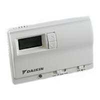
Terminal Designator Descriptions
Parts Diagram
R12
W1
Y1 W2 O
S1
S2
668375401
Y2
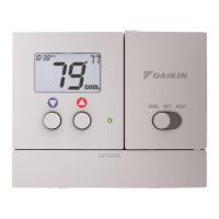
BacklitDisplay
Reset
CongurationSwitches ModeSwitch FanSwitch
Configuration Mode
ThecongurationmodeisusedtosettheDaikinAuto-changeoverElectronicThermostattomatch
yourheating/coolingsystem.
ToconguretheDaikin
Auto-changeoverElectronicThermostat
,perform
thefollowingsteps:
1. Removethecoverofthethermostatbygentlypullingononeofthecorners.
2. S
imultaneouslyholdtheSW5andSW6buttonsinfor5secondswhiletheDaikin
Auto-changeover
ElectronicThermostat
isinOFFmode.
3. Pressthe or buttontochangesettingswithineachscreen.
4. Pressthe
SW6
buttontoadvancetothenextscreen.
Note:The
SW5
button will return you to the previous screen.
5. Toexitcongurationmode,slidetheModeswitchtoHeatorCool.
FILTER
DIFF
ROOM
SET
REMOTE
Conguration Mode Settings
ThesetupscreensforCongurationModeareasfollows:
1. Heat Pump and Non Heat Pump –Pressthe
or buttontocongureas
heatpump,ornon-heatpumpsystem.Setto“O”forallDaikinWSHP,PTAC,
PTHPandUVunits.
Pressthe
SW6
buttontoadvancetothenextscreen.
FILTER
DIFF
ROOM
SET
REMOTE
2. Setto“g”.
Pressthe or buttontosetto“g”.
Pressthebuttontoadvancetothenextscreen.
FILTER
DIFF
ROOM
SET
REMOTE
3. Temperature Scale (F or C) –ChooseFahrenheitorCelsius.
Pressthe or buttontoselect.
Pressthe
SW6
buttontoadvancetothenextscreen.
-C–24VAC/VDCcommon
+R–24VAC/VDChot
W1–1ststageheat
Y1–1ststagecool
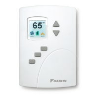
Remote Sensor Installation (Optional)
Requires Daikin Remote Sensor Part Number 667720401
1. Removecoverfromremotesensorhousing.
2. Selectanappropriatelocationformountingtheremotesensor.
3. Mountremotesensorunitusinghardwareprovided.
4. Installtwostrandshieldedwirebetweenremotesensorandthermostat.Shieldedwiremustbe
used.Donotrunremotesensorwireinconduitwithotherwires.
• Wire 1shouldrunbetweentheS1terminalonthethermostatandtheS1terminal
ontheremotesensor
• Wire 2shouldrunbetweentheS2terminalonthethermostatandtheS2terminal
ontheremotesensor
• ConnecttheshieldingofthewiretotheS2terminalonthethermostat
5. Disablethemainsensor(R12)onthethermostatbycuttingitfromthecircuitboard.
FILTER
DIFF
ROOM
SET
REMOTE
FILTER
DIFF
ROOM
SET
REMOTE
5. 2
nd
StageTemperature Differential
(1°Fto6°F)(0.5°Cto3.0°C)
Setthenumberofdegreesbetweenwhenstage1turnsonand
whenstage2turnson.
Pressthe
or buttontosetdifferentialvalue.
Pressthe
SW6
buttontoadvancetothenextscreen.
FILTER
DIFF
ROOM
SET
REMOTE
FILTER
DIFF
ROOM
SET
REMOTE
4. 1
st
StageTemperature Differential
(1°Fto3°F)(0.5°Cto1.5°C)
Setthenumberofdegreesbetweenyour“setpoint”temperature
andyour“turnon”temperature.
Pressthe
or buttontosetdifferentialvalue.
Pressthe
SW6
buttontoadvancetothenextscreen.
W2–2ndstageheat
Y2–2ndstagecooling
G–Fan
O–Override
Wiring Diagram
24 VAC Common
Tenant Override
Fan
Cool 1
Cool 2
Heat 1
Heat 2
Alarm Output
24 VAC
C
O
G
Y1
Y2
W1
W2
A
R
Override (Optional)
Thermostat
Terminals
TB2
MicroTech III Unit Control Board
Low Voltage Terminal Strip (Circuit 1)
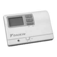
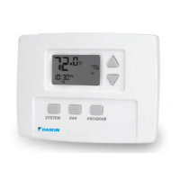
Non-Programmable, Auto or Manual Changeover (P/N 668375401)
Two Stage Heat/Two Stage Cool, Night Setback and Override Feature
Note: An additional conductor is required between “O” terminals for the override
feature to work.
Installation, Operation & Application Guide
Version B: 10-15-13
Daikin P/N (668375401)
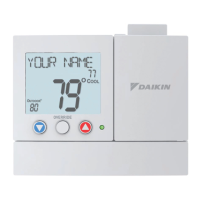
2 Heat/2 Cool, Auto or Manual Changeover, Hardwired
Non-Programmable Electronic Thermostat
• Configurable
• Two Stage Heat / 2 Stage Cool
Systems
• Backlit Display
• Field Temperature Calibration
• Status Indicator Light
• Relay Outputs (minimum voltage drop
in thermostat)
• Night Set-Back Override
• Reset