25
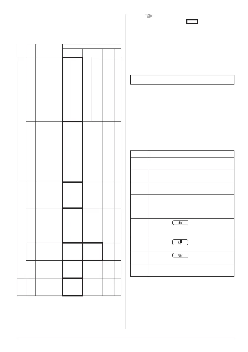
(Example)
Ifthetimetocleanairlterissetto“Filter
Contamination-a lot”, set MODE NO. to “10”,
FIRST CODE NO. to “0”, and SECOND CODE
NO. to “02”.
MODE
NO.
FIRST
CODE
NO.
DESCRIPTION
OF SETTING
SECOND CODE NO. NOTE)
01 02 03 04
10
0
Filter
Contamination a
little/a lot
(Setting for
spacing time of
display time to
cleanairlter)
(Setting for
whenlter
contamination is
a lot, and
spacing time of
display time to
cleanairlteris
to be halved)
a
little
(Light)
Approx.
200
hrs.
a lot
(heavy)
Approx.
100
hrs.
– –
3
Spacing time of
display time to
cleanairlter
count (Use
“Without
indication”
setting when
cleaning
indication is not
necessary such
as the case of
periodical
cleaning being
carried out.)
With
indication
(Display)
Without
indication
(Do not
display)
– –
12
1
ON/OFF input
from outside
(Set to enable
starting/
stopping from
remote.)
Forced
OFF input
ON/OFF – –
2
Thermostat
differential
changeover
(Set when using
remote
controller
thermostat
sensor.)
1°C 0.5°C – –
6
Fan speed
during cooling
thermostat-
OFF
LL
(Extra Low)
Setting – –
3
Fan speed
during heating
thermostat-
OFF
LL
(Extra Low)
Setting – –
13 0
Airowrate
increase mode
(to be set upon
user’s request)
Standard
Slightly
increase
Increase
–
NOTE
• The settings shown by “ ” in the table
indicate those when shipped from the factory.
Do not perform setting that are not listed in the
table.
For group control with a wireless remote controller,
initial settings for all the indoor units of the group
are equal. (Refer to the installation manual
attached to the indoor unit for group control.)
4. TEST OPERATION
• Perform test operation according to the
instructions in the installation manual attached
to the indoor unit and outdoor unit.
• After completing the refrigerant piping, drain
piping, and electrical wiring, perform test
operation in accordance with the procedure
shown on Table 4 in order to protect the unit.
(Refer to the installation manual attached to the
outdoor unit for VRV system types.)
Table 4
Order Operation description
(1)
Completely open the stop valve on gas
side.
(2)
Completely open the stop valve on
liquid side.
(3)
Turn the power on at least 6 hours
before operating the unit.
(4)
Set to the cooling operation using the
remote controller, and then start the
operation by pressing the ON/OFF
button.
(5)
Press the
button 2 times, and
let the operation continue for 3 minutes
in the test operation mode.
(6)
Press the
button to check the
actuation.
(7)
Press the
button 1 time to
return to normal operation mode.
(8)
Check the functions in accordance with
operation manual.
[PRECAUTIONS]
• If it does not operate, check the malfunction
code according to the instruction in the
operation manual attached to the Wireless
Remote Controller Kit, and conduct the failure
diagnosis referring to <MALFUNCTION CODE
LIST> in the installation manual of the indoor
unit and outdoor unit.
01_EN_4P457494-6L.indd 25 13/03/2019 11:07:55