English 9
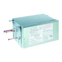
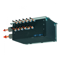
• Table 5 lists BS unit connection pipe size.
Table 5 BS unit connection pipe size
Unit: mm
BS unit
Outdoor unit side (*1) Indoor unit side (*2)
Suction pipe HP/LP gas pipe Liquid pipe Gas pipe Liquid pipe
BS4Q14AV1
ϕ22.2 (ϕ19.1) ϕ19.1 (ϕ15.9) ϕ9.5
ϕ12.7 (ϕ15.9) ϕ6.4 (ϕ9.5)
BS6Q14AV1
ϕ28.6
ϕ19.1 (ϕ22.2) ϕ12.7
BS8Q14AV1
ϕ19.1 (ϕ22.2, ϕ28.6) ϕ12.7 (ϕ15.9)
BS10Q14AV1
ϕ28.6 (ϕ34.9)
ϕ28.6
ϕ15.9
BS12Q14AV1
ϕ15.9 (ϕ19.1)
BS16Q14AV1
ϕ34.9 ϕ19.1
*1 Figures in parentheses indicate the size of the accessory pipes. If the pipe size differs from that of the
size selected from Table 3, you will need a reducing joint (to be supplied in the eld).
*2 The pipe diameter in parentheses can be used by cutting the pipes on the BS unit side with a pipe cut-
ter. For details, refer to “6-3 Piping connection.”
NOTES
• If the number of indoor units to be connected is less than the number of branch ports (so that there are
empty branch ports left, or if you plan to increase the number in the future), any of the branch ports can
be left open.
• If you plan to add new indoor units in the future, select a pipe size based on the total indoor unit capacity
before addition of new units.
• Be sure to use the stop valve kit for extension (KHFP26M224, sold separately) for pipe that you plan to
expand in the future. Do not size pipe based on anticipated future expansion. Instead, reexamine the pipe
size when you expand the system.
Failure to use the stop valve kit for extension will force you to recover the refrigerant before connecting
any new indoor units.
• For more information about how to install the stop valve kit for extension, refer to the installation manual
included with the stop valve kit for extension.
6-2 Pipe connection work precautions
Connect the pipes.
• Braze (*2) refrigerant pipes after nitrogen replacement (replacing air and nitrogen while allowing nitrogen
to ow inside the refrigerant pipe (*1). (Refer to Fig. 2))
(*1) The pressure regulator for the nitrogen released when doing the brazing should be set to about 0.02
MPa (enough to feel a slight breeze on your cheek).
(*2)
Do not use ux when brazing the refrigerant pipe.
Use phosphor copper (BCuP-2: JIS Z 3264/B-Cu93P-710/795: ISO 3677), which does not require
ux, as the ller metal for brazing.
(Using chlorine ux may cause the pipes to corrode, and if it contains uoride it may cause the refrig-
erant lubricant to degrade, adversely affecting the refrigerant piping system.)
01_EN_3P194121-8U.indd 9 2/21/2014 3:31:07 PM