8 English
6-1 Pipe size selection
Select the size of piping between the outdoor unit (refrigerant branch kit) and the BS unit and between the
BS unit and indoor units (refrigerant branch kits) based on example connections 1 and 2 below and Tables
3 through 5.
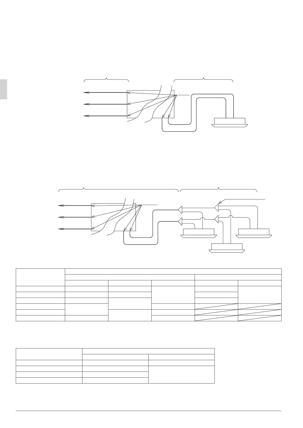
Example connection 1 : When connecting 1 indoor unit downstream of the BS unit
Upstream Downstream
Downstream
Indoor unit
BS unit
Suction gas pipe
HP/LP gas pipe
Liquid pipe
Liquid pipe
Gas pipe
To outdoor unit
or refrigerant
branch kit
Table 5
Select a size from Table 3 based on the
total capacity of the indoor units to be
connected downstream.
Select a size from Table 4 based on the
indoor unit capacity type.
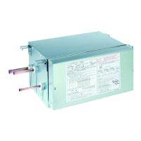
Example connection 2 : When there is a branch downstream from the BS unit
Select a size from Table 3
based on the total capacity
of the indoor units to be
connected downstream.
Refer to the installation manual
included with the outdoor unit or the
equipment design materials to deter-
mine the size of the pipes between the
BS unit and the refrigerant branch kits
and between the refrigerant branch
kits and indoor units.
Upstream
Suction gas pipe
HP/LP gas pipe
Liquid pipe
BS unit
Downstream
Indoor unit Indoor unit
Indoor unit
Refrigerant branch kit
Liquid pipe
Gas pipe
Table 5
To outdoor unit
or refrigerant
branch kit
Table 3 Total indoor unit capacity and pipe size Unit: mm
Total indoor unit capacity
(Q)
Pipe size (outside diameter × minimum thickness)
Upstream Downstream
Suction pipe HP/LP gas pipe Liquid pipe Gas pipe Liquid pipe
Q < 150
ϕ15.9 × 1.0 ϕ12.7 × 0.8
ϕ9.5 × 0.8
ϕ15.9 × 1.0
ϕ9.5 × 0.8
150 ≤ Q < 200
ϕ19.1 × 1.0 ϕ15.9 × 1.0 ϕ19.1 × 1.0
200 ≤ Q < 290
ϕ22.2 × 1.0
ϕ19.1 × 1.0
ϕ22.2 × 1.0
290 ≤ Q < 420
ϕ28.6 × 1.0
ϕ12.7 × 0.8
420 ≤ Q < 640
ϕ28.6 × 1.0
ϕ15.9 × 1.0
640 ≤ Q ≤ 750
ϕ34.9 × 1.2 ϕ19.1 × 1.0
• In case of connection to the main pipe, refer to the installation manual included with the outdoor unit or
the equipment design materials.
Table 4 Indoor unit connection pipe size
Unit: mm
Indoor unit capacity type
Pipe size (outside diameter × minimum thickness)
Gas pipe Liquid pipe
20, 25, 32, 40, 50
ϕ12.7 × 0.80 ϕ6.4 × 0.80
63, 80, 100, 125
ϕ15.9× 1.0
ϕ9.5 × 0.80
200
ϕ19.1 × 1.0
250
ϕ22.2 × 1.0
01_EN_3P194121-8U.indd 8 2/21/2014 3:31:07 PM