SYSTEM OPERATION
22
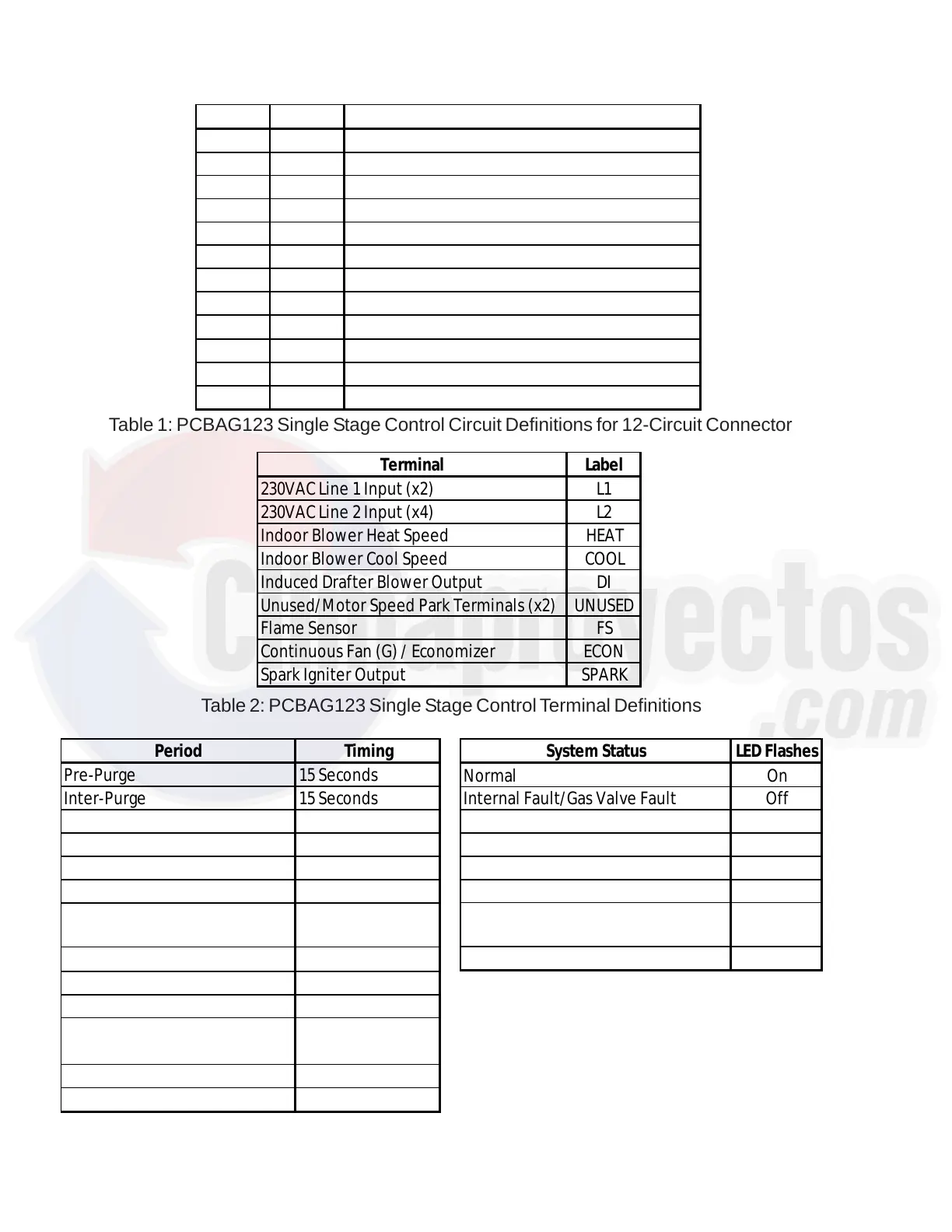
Table 1: PCBAG123 Single Stage Control Circuit Definitions for 12-Circuit Connector
Terminal Label
230VAC Line 1 Input (x2) L1
230VAC Line 2 Input (x4) L2
Indoor Blower Heat Speed HEAT
Indoor Blower Cool Speed COOL
Induced Drafter Blower Output DI
Unused/Motor Speed Park Terminals (x2) UNUSED
Flame Sensor FS
Continuous Fan (G) / Economizer ECON
Spark Igniter Output SPARK
Table 2: PCBAG123 Single Stage Control Terminal Definitions
Table 3: PCBAG123 Single Stage Control
Timings
Table 4: PCBAG123 Single Stage Control
LED Status Codes
Period Timing
Pre-Purge 15 Seconds
Inter-Purge 15 Seconds
Post Purge 29 Seconds
Trial-for-Ignition (TFI) 7 Seconds
Flame Stabilization Period 10 Seconds
Heat ON Delay 30 Seconds
Heat OFF Delay
Selectable 120, 135
or 150 Seconds
Cool ON Delay 7 Seconds
Cool OFF Delay 60 Seconds
Ignition Attempts 3 Attempts
Recycles Infinite
4 Recycles
(5 Flame Losses)
Automatic Restart 60 Minutes
Compressor Short Cycle Delay 3 Minutes
System Status LED Flashes
Normal On
Internal Fault/Gas Valve Fault Off
Ignition Lockout 1
Pressure Switch Stuck Open 2
Pressure Switch Stuck Closed 3
Open High Temperature Limit 4
Flame Detected with Gas Valve
De-Energized
5
Compressor Short Cycle Delay Active 6
Pin Voltage Function
1 24VAC 24VAC Input (from Transformer)
2 24VAC 24VAC Common (Chassis Ground)
3 24VAC Gas Valve Output
4 24VAC Limit Switch Output
5 24VAC Limit Switch Input (Common with Pin 9)
6 24VAC Pressure Switch Input
7 24VAC Thermostat Fan (G) Input
8 24VAC Pressure Switch Output (Common with Pin 10)
9 24VAC Thermostat "R" (Common with Pin 5)
10 24VAC Thermostat Heat Input (W) (Common with Pin 8)
11 24VAC Thermostat Cool Input (Y)
12 24VAC Compressor Contactor Output
 Loading...