SERVICING
58
S-311 HIGH ALTITUDE APPLICATION
High Altitude Derate - U.S. Installations Only
IMPORTANT NOTE: The gas/electric units naturally derate
with altitude. Do not attempt to increase the firing rate by
changing orifices or increasing the manifold pressure. This
can cause poor combustion and equipment failure. At all
altitudes, the manifold pressure must be within 0.3 inches
W.C. of that listed on the nameplate for the fuel used. At all
altitudes and with either fuel, the air temperature rise must
be within the range listed on the unit nameplate. Refer to the
Installation Manual provided with the LP kit for conversion
from natural gas to propane gas and for altitude adjustments.
When this package unit is installed at high altitude, the
appropriate High Altitude orifice kit must be installed. As
altitude increases, there is a natural reduction in the density
of both the gas fuel and combustion air. This kit will provide
the proper design certified input rate within the specified
altitude range. High altitude kits are not approved for use in
Canada. For installations above 2,000 feet, use kit HA-03.
The HA-03 kit is used for both Natural and LP gas at high
altitudes.
Use LPM-08 (2 stage heat models) or LPM-07 (1 stage heat
models) propane conversion kit for propane conversions at
altitudes below 2000 feet. Natural gas installations below
2000 feet do not require a kit.
For propane conversions above 2000 feet, high altitude kit
HA-03 is required in addtion to the propane conversion kit.
Natural gas and LP gas installations at altitudes > 2000 ft
2000 3000 4000 4500 5000 6000 7000 8000
U.S. BURNER ORIFICE 46/1.25MM 47/1.25MM 47/56 - 48/56 48/57 49/57 49/57
CANADA BURNER ORIFICE - - - 48/56 - - - -
ELEVATION ABOVE SEA-LEVEL (FEET)
20,000 BTUH NAT/18,OOO BTUH LP
INPUT/BURNER
HIGH ALTITUDE
KIT
HA-03
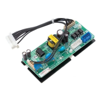
S-313 TESTING IGNITION CONTROL MODULE
NOTE: Failure to earth ground the unit, or a high resistance
connection in the ground may cause the control to lockout
due to failure to flame sense.
Testing Direct Spark Ignition (DSI) systems
Thermostat calling for heat (15 second prepurge time and 7
second trial for ignition).
1. Check for 230 VAC from L1 terminal of control module to
L2. No voltage - check wire connections, continuity, etc.
2. Check for 24 VAC at "R" to "C" thermostat terminals.
a. No voltage - check 3 amp automotive type fuse on
control board. A blown fuse would indicate a short
in the 24 VAC circuit (thermostat or limit circuit).
b. Voltage Present - check limit, auxiliary limit and
rollout (S-300, S-301 and S-302). If limit, auxiliary
limit and rollout are closed, then check for 24 VAC
at the gas valve terminals.
No 24 VAC at gas valve - replace Control board.
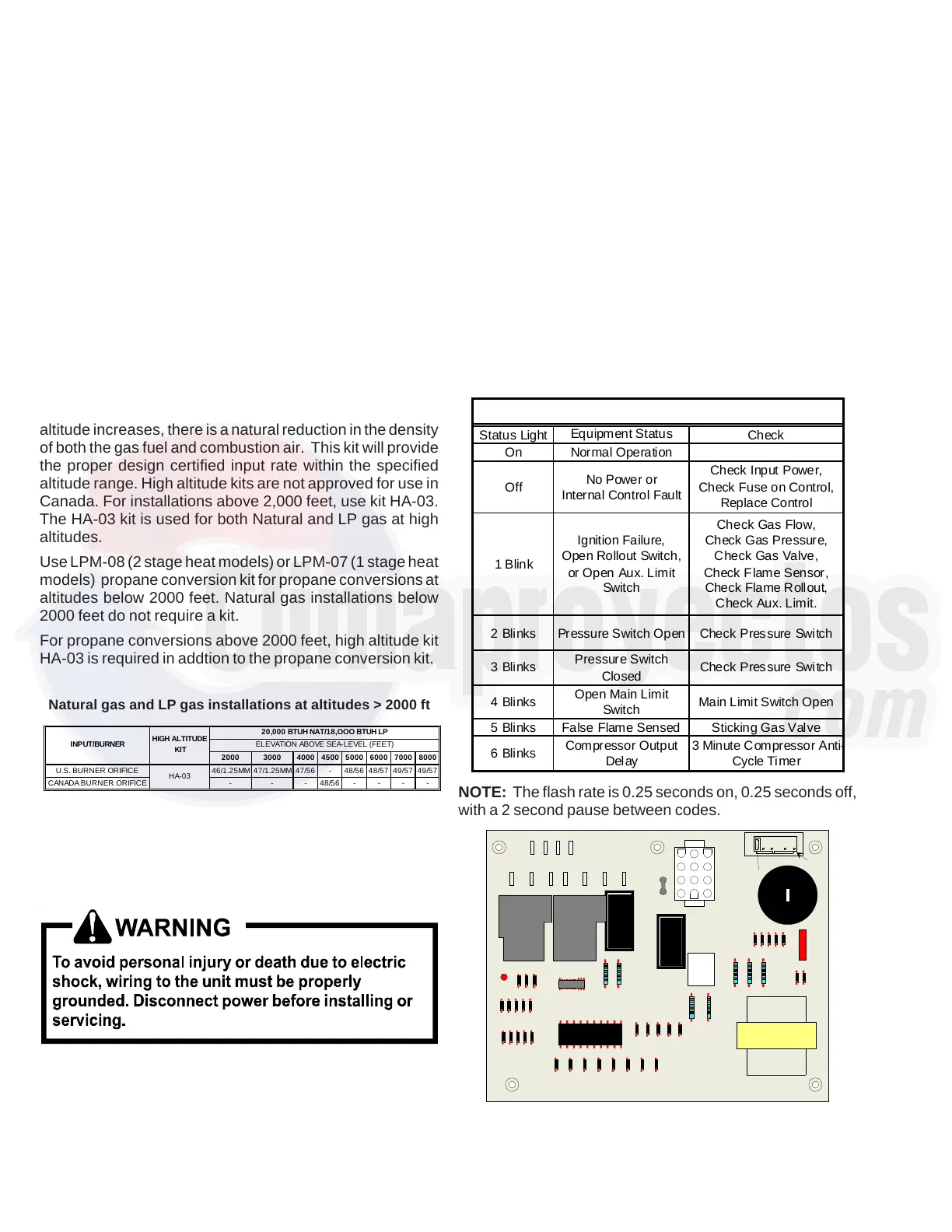
Status Light
Equipment Status
Check
On Normal Operation
Off
No Power or
Internal Control Fault
Check Input Power,
Check Fuse on Control,
Replace Control
1 Blink
Ignition Failure,
Open Rollout Switch,
or Open Aux. Limit
Switch
Check Gas Flow,
Check Gas Pressure,
Check Gas Valve,
Check F lame Sensor,
Check Flame Rollout,
Check Aux. Limit.
2 Blinks Pressure Switch Open Check Pressure Switch
3 Blinks
Pressure Switch
Closed
Check Pressure Switch
4 Blinks
Open Main Limit
Switch
Main Limit Switch Open
5 Blinks False Flame Sensed Sticking Gas Valve
6 Blinks
Compressor Output
Delay
3 Minute Compressor Anti
Cycle Timer
PCBAG123 Ignition Board Fault Codes
NOTE: The flash rate is 0.25 seconds on, 0.25 seconds off,
with a 2 second pause between codes.
3
2
1
6
54
9
8
7
12
11
10
L2 L2 L2
L2
COOL HEAT
UNUSED
L1
L1 D1
FS
Diagnostic LED
Blower Off Delay Settings
Transformer
speed up
PCBAG123 DSI Control Board