Gas Piping Routing Into Unit
On-The-Roof Piping
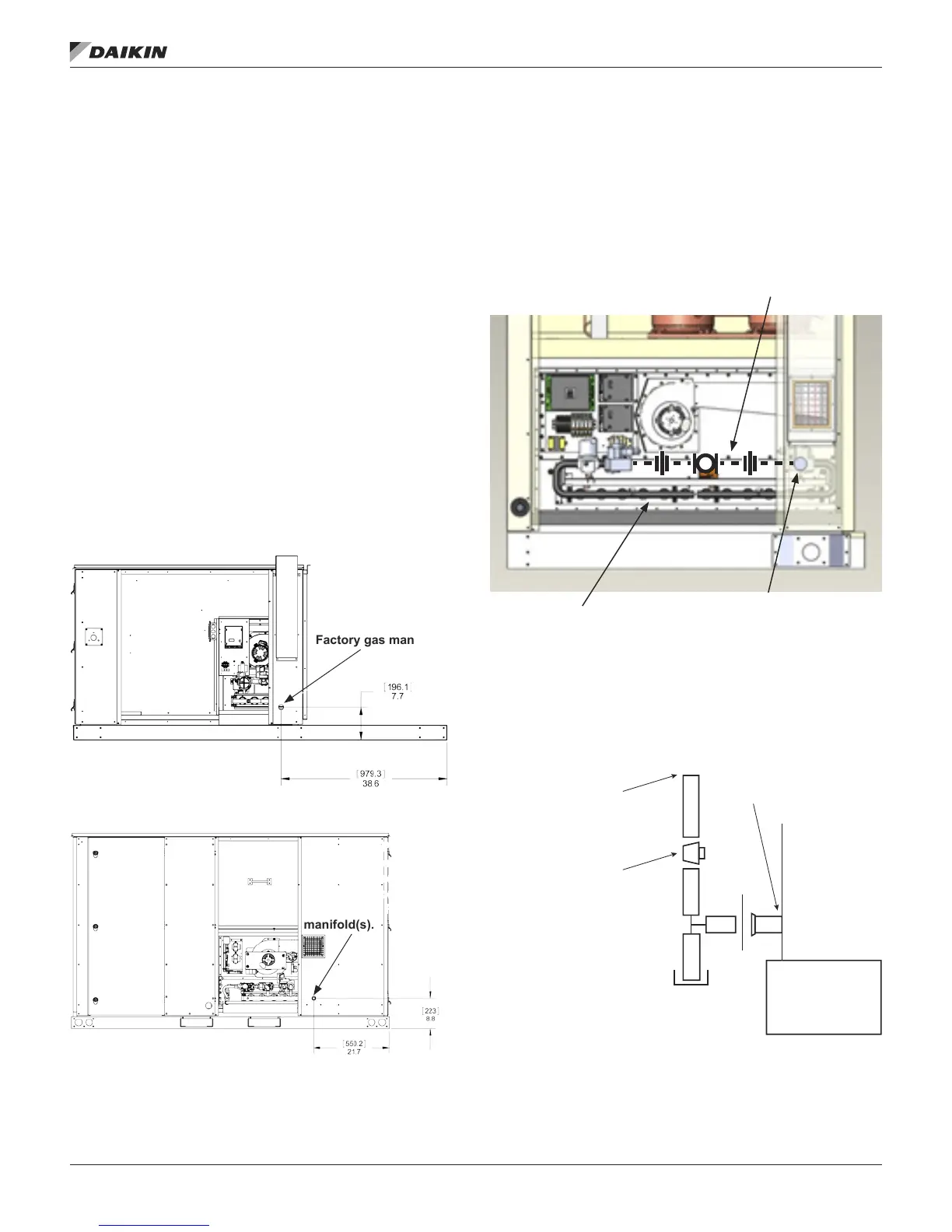
1. Remove knockout on upright (refer to Figure 46, Figure
47 or Figure 48).
2. Route gas supply pipe through hole. Carefully plan pipe
route and tting locations to avoid interference with
swinging of doors, etc.
3. The Rebel unit does not have an option for gas piping
through the curb.
4. Field piping to be supported such that it does not
generate a force (weight) and/or torque (twist) on the
Factory gas manifold(s).
The appliance must be isolated from the gas supply system by
closing off the manual shut off valve during any pressure testing
less than 0.5 psi (3.5 kPa) of the gas supply piping system.
The appliance and its individual shut-off valve must be
disconnected from the gas supply system during any pressure
testing greater than or equal to 0.5 psi (3.5 kPa).
Regulator to be sized for the maximum total Btu input required
for the heater(s).
Figure 46: Rebel A Cabinet 003–006 Gas Piping
Figure 47: Rebel B Cabinet 007–015 Gas Piping
Figure 48: Rebel C Cabinet 016–028 Gas Piping
Figure 49: Field Gas Heat Connections
Field Piping. Piping to
be supported such that
if does not generate
force (weight) and/or
torque (twist) on the
Factory gas manifold(s).
Field Piping. Piping to be
supported such that if
does not generate force
(weight) and/or torque
(twist) on the Factory gas
manifold(s).
Field Piping. Piping to
be supported such that
if does not generate
force (weight) and/or
torque (twist) on the
Factory gas manifold(s).
Field piping entrance
point into cabinet
Factory gas manifolds
From Gas Meter
Unit Gas Supply
Connection*
Manual Gas
Shut-Off Valve
with 1/4" NPT
Test Plug
* Factory-supplied grommet must be utilized
IM 1125-7 • REBEL ROOFTOPS 46 www.DaikinApplied.com
opTIonal gas heaT