12
13 ACHIEVING 1.4% AND 2.0% AIRFLOW LOW
LEAKAGE RATE
Ensure all the gaskets remain intact on all surfaces as shipped
with the unit. These surfaces are areas between the upper tie
plate and coil access panel, blower access and coil access
panels, and between the coil access and lter access pan-
els. Ensure upon installation, that the plastic breaker cover
is sitting ush on the blower access panel and all access
panels are ush with each other and the cabinet. With these
requirements satised, the unit achieves less than 1.4%
airow leakage @ 0.5 inch wc static pressure and less than
2% airow leakage @1inch wc static pressure when tested
in accordance with ASHRAE Standard 193.
IMPORTANT: After installing the heater kits, it is very import-
ant to seal the gap between the circuit breaker and the cover.
Putty paste or gasket can be used to seal the gap so that air
leakage can be minimized.
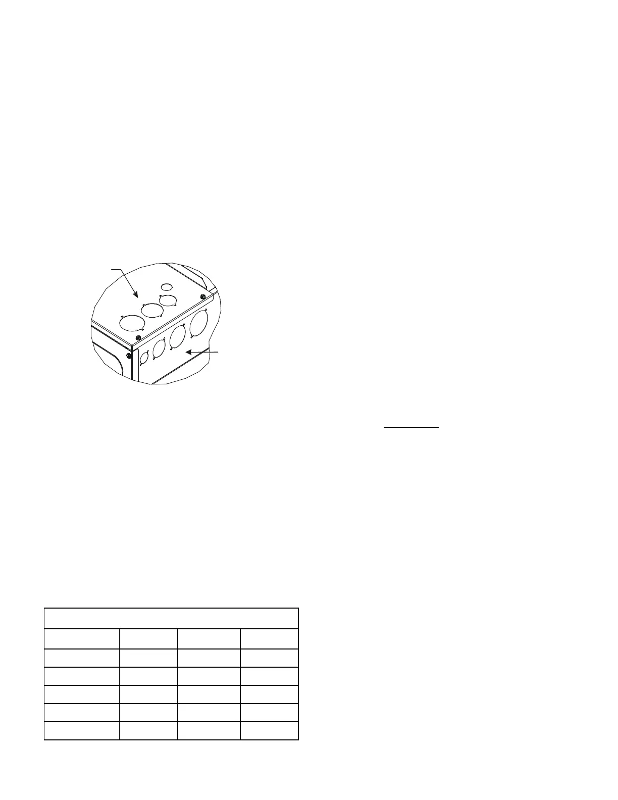
Side of
Cabinet
Top of
Cabinet
KNOCK-OUT FOR ELECTRICAL
CONNECTIONS
Figure 14
14 AIRFLOW TRIM
Indoor airow can be trimmed up/down through the outdoor
unit user menu. For more detailed information, please refer
to the outdoor unit installation manual.
• To prevent condensation blow off, positive side trim
settings are allowed within the Maximum CFM listed
below. The CFM in this table intends actual measured
value at installation site. Do not refer to the CFM value
in the outdoor spec sheet, displayed in status menu
of communication thermostat, or the displayed LEDs
on the PCB, as there may be a tolerance difference
between displayed and actual measured.
Maximum Measured CFM Allowed
Up-Flow Down-Flow HZ-Flow
DV24FECB14 910 870 870
DV36FECC14 1450 1390 1390
DV42FECC14 1520 1450 1450
DV48FECD14 1590 1520 1520
DV60FECD14 1890 1800 1800
15 MISCELLANEOUS START-UP CHECKLIST
• Prior to start-up, ensure that all electrical wires are prop-
erly sized and all connections are properly tightened.
• All panels must be in place and secured. For Air Tight
application, gasket must be positioned at prescribed
locations to achieve 2% leakage.
• Tubing must be leak free.
• Condensate line must be trapped and pitched to allow
for drainage.
• Auxiliary drain is installed when necessary and pitched
to allow for drainage.
• Low voltage wiring is properly connected.
• Unit is protected from vehicular or other physical dam-
age.
• Return air is not obtained from, nor are there any return
air duct joints that are unsealed in, areas where there
may be objectionable odors, ammable vapors or prod-
ucts of combustion such as carbon monoxide (CO),
which may cause serious personal injury or death.
IMPORTANT NOTE: If thumb screws are used to access the
lter, ensure the washer installed on the screw behind the
access panel remains in place after re-installation.
NOTE: A removable plug connector is provided with the
control to make thermostat wire connections. This plug
may be removed, wire connections made to the plug, and
replaced. It is STRONGLY recommended that you do not
connect multiple wires into a single terminal. Wire nuts are
recommended to ensure one wire is used for each terminal.
Failure to do so may result in intermittent operation.