Do you have a question about the Daikin DX17VSS181AA and is the answer not in the manual?
| Model | DX17VSS181AA |
|---|---|
| SEER Rating | 17 |
| Energy Efficiency Ratio (EER) | 12.5 |
| Refrigerant | R-410A |
| Voltage | 208/230 V |
| Phase | 1 |
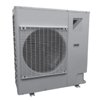
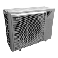
| Type | Air Conditioner |
| Stages | Variable |
| Outdoor Unit Dimensions (HxWxD) | 35" |
| Cooling Capacity | 18000 BTU/h |
Verifies model, specifications, and accessories are correct prior to installation.
Installation must comply with national and local codes/regulations.
Describes inverter technology and thermostat compatibility.
Guidelines for choosing a suitable location for the outdoor unit.
Steps to ensure secure and proper installation of the unit.
Specifies required clearances around the outdoor unit for airflow.
Considerations for installing the unit on a roof structure.
Minimizing electrical noise effects on other equipment.
Explains hazard symbols and their meanings for safety warnings.
Warnings and precautions related to the safe handling of refrigerants.
Safety precautions for using and storing refrigerant cylinders.
Caution regarding compressor oil susceptibility to moisture and potential damage.
Table showing permitted refrigerant line set diameter combinations.
General guidelines for installing refrigerant lines, including insulation and contact avoidance.
Describes inverted loop requirement for suction line when condenser is below evaporator.
Describes oil trap requirement when condenser is above evaporator.
Details on constructing an oil trap from standard refrigerant fittings.
Precautions to avoid overheating and damage during refrigerant line brazing.
Procedure for leak testing the system using nitrogen or a leak detector.
General notes and procedures for initiating system operation.
Instructions for high voltage and grounding connections, and overcurrent protection.
Information on protecting the unit from overcurrent conditions.
Method for calculating refrigerant charge based on line set length and diameter.
Cautions regarding proper valve opening sequence to avoid oil or refrigerant loss.
Notification that a system test is required at startup for equipment verification.
Procedure to set the thermostat to CHARGE MODE for system charging.
Instructions for adding or recovering refrigerant based on Step 1 calculation.
Procedure for measuring subcooling to verify correct refrigerant charge.
Notices regarding checking Schrader ports and not adjusting charge by suction pressure.
Enables system operation at increased speeds to satisfy high loads.
Tips for effective dehumidification operation and settings.
Enables system operation at decreased speeds for quiet operation.
Describes the ComfortNet system's digital communication and components.
Instructions on accessing advanced feature menus and system settings.
Access to recent faults and troubleshooting information.
Displays current system status for troubleshooting and verification.
Details on advanced menus for diagnostics, status, system setup, and cool setup.
Allows configuration of Boost Mode, Night Mode, and other system parameters.
Enables mandatory system verification tests for functional checks.
Options for system maintenance, including charge mode.
Adjustments for cooling performance variables like airflow and delays.
Settings for maximum compressor RPM range and selection for cooling.
Warning regarding high voltage hazards during wiring installation.
Safety warning for handling capacitors due to residual voltage.
Chart correlating possible causes with cooling performance indicators.
Table listing fault codes, messages, probable causes, and corrective actions.
Diagnosing communication issues using LED indicators and dipswitch settings.
Introduction to the 3-digit PCB display for fault reading and setup.
Description of buttons used to navigate the display interface.
Explanation of the five modes: Fault Code, History, Monitoring, Setting 1, Setting 2.
Instructions on how to navigate through the different display screens.
Procedure for accessing and viewing the six most recent system faults.
Instructions for monitoring system variables in the display.
Procedure for adjusting system settings in Mode 1.
Procedure for adjusting system settings in Mode 2.
Displays the current fault code if one is present.
Displays the six most recent fault codes recorded.
Allows monitoring of system variables and operational data.
Provides access to adjust system settings in Mode 1.
Provides access to adjust system settings in Mode 2.
Recommendations for maintaining the indoor air filter for system efficiency.
Guidelines for cleaning the outdoor coil by a qualified servicer.
Troubleshooting steps to perform before calling a qualified servicer.
Checklist of tasks to complete before initial unit start-up.
Fields to record electrical, blower, temperature, and pressure values during start-up.