EasyManua.ls Logo

Daikin DX17VSS601AA User Manual

Daikin DX17VSS601AA
156 pages
To Next Page IconTo Next Page
Page #1 background imageLoading...
Page #1 background image
INSTALLATION INSTRUCTIONS
AIR CONDITIONER
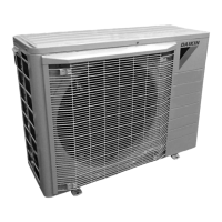
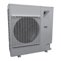
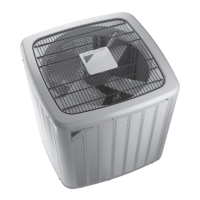
DX17VSS AIR CONDITIONING
INSTALLATION & SERVICE REFERENCE
Index
Important Safety InStructIonS ............................................. 1
ShIppIng InSpectIon .............................................................. 1
codeS & regulatIonS .......................................................... 2
featureS.............................................................................. 2
Before InStallatIon .............................................................2
precautIonS for SelectIng a locatIon ................................. 2
precautIonS for InStallatIon ............................................... 3
InStallatIon clearanceS ......................................................3
rooftop InStallatIonS .........................................................3
electrIcal noISe ................................................................. 4
Safety conSIderatIonS......................................................... 4
refrIgerant lIneS ............................................................... 6
refrIgerant lIne connectIonS ............................................. 8
leak teStIng (nItrogen or nItrogen-traced) ...................... 8
SyStem Start-up procedure ................................................ 9
Start-up procedure detaIl .................................................. 9
electrIcal connectIonS ......................................................9
calculate refrIgerant charge BaSed on lIne Set length
... 12
connect aIr condItIoner to SyStem .................................. 13
SyStem Start-up teSt (In caSe of ctk04) ........................ 14
Set thermoStat to charge mode (In caSe of ctk04)
... 17
adjuSt refrIgerant level .................................................20
meaSure SuBcoolIng to verIfy proper charge ................. 20
fIeld SelectaBle BooSt mode (In caSe of ctk04) ........... 21
dehumIdIfIcatIon (In caSe of ctk04) ................................. 24
nIght mode (In caSe of ctk04) ........................................ 25
comfortnet™ SyStem .......................................................28
aIr condItIoner advanced feature menu ........................... 30
WIrIng dIagram ................................................................ 33
teStIng capacItor reSIStance ............................................34
coolIng analySIS chart .................................................... 35
trouBleShootIng ...............................................................36
SettIng the mode dISplay .................................................. 41
7-Segment dISplay ............................................................. 47
aIr condItIonIng homeoWnerS routIne maIntenance
recommendatIonS ........................................................ 49
Start up checklISt ........................................................... 50
Important Safety InStructIonS
The following symbols and labels are used throughout this
manual to indicate immediate or potential safety hazards. It is
the owner’s and installer’s responsibility to read and comply
with all safety information and instructions accompanying
these symbols. Failure to heed safety information increases
the risk of personal injury, property damage, and/or product
damage.
WARNING
HIGH VOLTAGE !
dISconnect all poWer Before ServIcIng.
multIple poWer SourceS may Be preSent. faIlure
to do So may cauSe property damage, perSonal
Injury or death.
WARNING
only perSonnel that have Been traIned to InStall, adjuSt, Ser-
vIce or repaIr (hereInafter, “ServIce”) the equIpment SpecIfIed
In thIS manual Should ServIce the equIpment. the manufacturer
WIll not Be reSponSIBle for any Injury or property damage arIS-
Ing from Improper ServIce or ServIce procedureS. If you ServIce
thIS unIt, you aSSume reSponSIBIlIty for any Injury or property
damage WhIch may reSult. In addItIon, In jurISdIctIonS that re-
quIre one or more lIcenSeS to ServIce the equIpment SpecIfIed In
thIS manual, only lIcenSed perSonnel Should ServIce the equIp-
ment. Improper InStallatIon, adjuStment, ServIcIng or repaIr of
the equIpment SpecIfIed In thIS manual, or attemptIng to InStall,
adjuSt, ServIce or repaIr the equIpment SpecIfIed In thIS manual
WIthout proper traInIng may reSult In product damage, property
damage, perSonal Injury or death.
CAUTION
do not WaSh the aIr condItIoner WIth exceSSIve Water. an elec-
trIc Shock or fIre could reSult.
ShIppIng InSpectIon
Always keep the unit upright; laying the unit on its side or top
may cause equipment damage. Shipping damage, and sub-
sequent investigation is the responsibility of the carrier. Verify
the model number, specications, electrical characteristics,
and accessories are correct prior to installation. The distributor
or manufacturer will not accept claims from dealers for trans-
portation damage or installation of incorrectly shipped units.
English
Français
Español

Questions and Answers:

Daikin DX17VSS601AA Specifications

General IconGeneral
SEERUp to 17
HSPF9.0
StagesVariable Speed
RefrigerantR-410A
Voltage208/230 V
Phase1
TypeSplit System
Cooling Capacity60000 BTU/h
Heating Capacity60000 BTU/h
Dimensions (Indoor Unit)Varies with model
Dimensions (Outdoor Unit)35 x 31 x 29 inches
Indoor Unit Noise LevelVaries with model

Summary

Important Safety Instructions

High Voltage Warning

Disconnect all power before servicing to prevent property damage, personal injury or death.

Personnel Training Warning

Only trained personnel should service the equipment to prevent injury or damage.

Before Installation Precautions

Location Selection Guidelines

Guidelines for choosing a suitable installation location to ensure proper operation and minimize nuisance.

Installation Precautions and Clearances

General Installation Precautions

Check ground strength, use foundation bolts securely, and ensure unit is level.

General Safety Considerations

Refrigerant Handling Warnings

Safety precautions for handling refrigerants to avoid injury, explosion, or death.

Refrigerant Cylinder Safety

Guidelines for using service cylinders safely to prevent explosion.

Refrigerant Cylinder Safety Warnings

Explosion Prevention During Charging

Precautions to prevent explosions when handling refrigerant cylinders.

General Installation Safety Warnings

Improper Grounding Hazards

Critical warnings against improper grounding to prevent shock, leaks, or explosions.

Qualified Personnel Requirement

Emphasizes that only qualified personnel should perform installation work.

Refrigerant Lines and Tubing

Refrigerant Line Connections

Brazing Precautions and Torque Specs

Precautions for brazing, torque specs for valves and ports.

Leak Testing Procedures

Procedures and safety warnings for leak testing.

System Start-Up Procedures

Start-Up Warnings and Cautions

Critical warnings and cautions related to refrigerant pressure, suction valves, and refrigerant certification.

Detailed Start-Up Procedure

Electrical Connections and Safety

High Voltage and Conductor Safety

Warnings about high voltage, proper conductor material, and grounding.

Electrical Installation Precautions

Phase-Advancing Capacitor and Protection Device Warnings

Precautions against phase-advancing capacitors and altering protection devices.

Improper Grounding and Wiring Warnings

Warnings against improper grounding and connecting ground wire to unsuitable points.

Power Circuit Requirements

Voltage and Dedicated Circuit

Ensuring correct voltage and a dedicated power circuit for unit connection.

Wiring Terminal Block Precautions

Precautions for wiring to terminal blocks, including shielding plate and crimp terminals.

Calculate Refrigerant Charge

Connect Air Conditioner to System

Valve Operation Cautions

Cautions to open liquid valve first, avoid leaks, and ensure valves are open.

System Start-Up Test (CTK04)

Initial System Test Requirement (E11)

Notice that E11 code signals the need to run an initial system test.

System Test Mandatory

Note stating that the system test must be run for all installations.

Set Thermostat to Charge Mode (CTK04)

Charge Mode Operation

Adjust Refrigerant Level

Measure Subcooling for Proper Charge

Subcooling Calculation Formula and Table

Formula for calculating subcooling and table for adjusting charge.

Field Selectable Boost Mode (CTK04)

Boost Mode Configuration

Dehumidification Settings (CTK04)

Night Mode Settings (CTK04)

Night Mode Control and Settings

System Diagnostics

System Setup Options

Boost and Charge Mode Configuration

Configuration of BOOST MODE temperature and enabling CHARGE MODE.

Equipment Test and Cool Setup

Equipment Test Procedure

Mandatory system verification test for functional check and stop valve position.

Cooling Setup Adjustments

Adjustments for cooling airflow trim, profiles, and delays.

Air Conditioner Advanced Feature Menu

Diagnostics Menu Overview

Overview of the diagnostics menu for accessing recent faults.

Status Menu Items

Overview of status items like Time Stamp, Mode, and Compressor Reduction Mode.

System Setup Menu Details

Boost and Night Mode Configuration

Configuration of BOOST MODE, BOOST TEMP, NIGHT MODE, and Noise Down Level.

Charge Mode Function

Enters CHARGE MODE for refrigerant charging, runs for 1 hour.

Equipment Test Procedure

System Verification Test Requirement

Mandatory 10-15 minute test required after installation.

Cool Setup Menu Options

Cooling Delays and Dehumidification

Settings for ON/OFF delays and enabling/disabling dehumidification.

Wiring Diagram

High Voltage Wiring Safety

High voltage warning: disconnect power before servicing to prevent shock or fire.

General Wiring Safety Notes

General wiring safety warnings, including using copper conductors and proper connections.

Testing Capacitor Resistance

Capacitor Safety Warning

Warning to avoid contact with charged areas and to measure residual voltage.

Cooling Analysis Chart

Cooling Performance Troubleshooting Guide

Chart correlating possible causes with cooling performance indicators.

Troubleshooting - Fault Codes E12 to E25

Troubleshooting - Fault Codes E26 to E45

Troubleshooting - Fault Codes E47 to E45

Fault Code and Description Columns

Headers for fault codes, PCB LEDs, thermostat messages, probable causes, and corrective actions.

Troubleshooting - System Test Fault (E11)

Run System Test Instruction

Indicates startup test required; installer must navigate to run System Test.

Troubleshooting - Network Issues

Network Communication Troubleshooting

Troubleshooting communication issues within the ComfortNet system network.

Mode Display Navigation and Functions

Display Screen Navigation Guide

Navigating Between Display Screens

Instructions for navigating between different display screens (0-4) using buttons.

Fault Code History Navigation

Monitoring Mode Navigation

Setting Mode 1 Navigation

Setting Mode 2 Navigation

7-Segment Display Screens

7-Segment Display Setting Modes

Unitary Inverter Start-Up Checklist

Unitary Inverter Start-Up Checklist Details

Related product manuals