ECFWEB6+ECFWER6
Microprocessor controller for fan coils
4PW17551-1B
Installation and operation manual
10
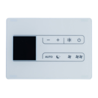
ECFWER6 INSTALLATION INSTRUCTIONS
Remote type controller
Installation
It is advisable to set the microswitches before installing
the controller, see paragraph "Setting the microswitches"
on page 10.
The remote controller can be installed to a wall.
Proceed as follows to fit the controller.
1 Remove the controller lock screw and remove the
cover.
2 Drill 2 holes in the wall where the controller shall be
installed, at the exact same position of the fixing slots
(5 x 8 mm) located on the control base (see figure 9).
3 Make the electric connections to the control terminal
board according to the wiring diagram of the selected
configuration.
4 By means of screws, fix the control base to the wall.
5 Reassemble the control cover part and make sure
the rotating knobs are in the same position as they
were upon disassembly. Secure the controller lock
screw back into place again.
6 Make the electric connections to the unit according to
the wiring diagram of the selected configuration.
SETTING THE MICROSWITCHES
1 Unscrew the controller lock screw from the bottom
side of the controller. Remove the front panel of the
controller.
2 Arrange the microswitches in the sequence
corresponding to one of the configurations explained
(see "Possible configurations" on page 7).
List of microswitches and their functions
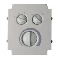
(See figure 7)
To facilitate its re-installation, be careful not to
modify the position of the 2 rotating knobs on
the controller cover (operating mode selector
switch and thermostat) and of the
corresponding potentiometers fit on the
electronic PCB.
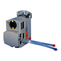
When installing the ECFWER6 controller on
units with a current consumption greater than
1 A, you must install an additional EPIMSA6
Master/Slave interface or EPIA6 Power
interface (see "Master/Slave interface and
Power interface" on page 11).
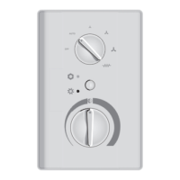
To facilitate its re-installation, be careful not to
modify the position of the 2 rotating knobs on the
controller cover (operating mode selector switch
and thermostat) and of the corresponding
potentiometers fit on the electronic PCB.
Micro-
switch
number
Function
Position
OFF ON
1
cooling/heating
switching
controller remote
2
cooling/heating
switching
manual automatic
3
automatic cooling/
heating switching
mode based on the
temperature of the
air water
4
range of the neutral
zone for the automatic
cooling/heating mode
based on the air
temperature
5°C 2°C
5
valve presence on
hydraulic circuit
— ✔
6
electric heater
presence
— ✔
7
number of pipes of
the hydraulic circuit
24
if the desired configuration does not include
the electric heaters control function and the
operating mode selector switch is turned to the
electric heater symbol, the fan coil will
continue to run with an automatic fan speed
and will regulate the air temperature by means
of the fan.
1B_I+OM_4PW17551-1B.book Page 10 Wednesday, October 5, 2005 9:18 AM
 Loading...