Installation and operation manual
13
4PW17551-1B
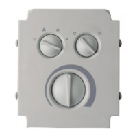
ECFWEB6+ECFWER6
Microprocessor controller for fan coils
The code of the terminals on ECFWEB6 controllers can
be found on the rear side of the plastic support.
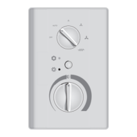
AUTODIAGNOSIS PROCEDURE
For checking the correct operational efficiency of the
controller when installing or for searching for possible
faults, all outputs can be operated manually (fan, valves,
electric heater) thanks to the autodiagnosis mode.
Proceed as follows to access the autodiagnosis mode
and to run the tests
1 Turn the operating mode selector switch to the "OFF"
position.
2 Turn the knob of the thermostat anti-clockwise until it
reaches the minimum temperature position.
3 Hold the cooling/heating selector pushed for at least
5 seconds. At this stage both LEDs light up.
4 Within 5 seconds, turn the knob of the thermostat
clockwise to the maximum temperature position. The
red LED switches off and the blue LED remains lit to
indicate that the autodiagnosis mode has been
accessed.
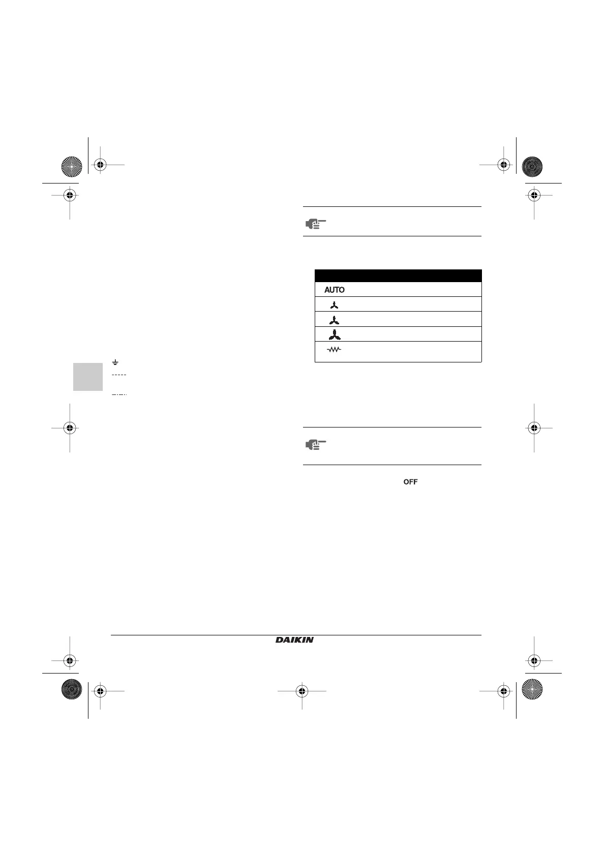
5 In the autodiagnosis mode, each position of the
operating mode selector switch corresponds to the
simulation of an output.
By running through the various positions of the
operating mode selector switch, the electronic
controller outputs can be checked one after the other
either by observing the related component (valve,
fan, electric heater) or by checking if the
corresponding terminals are powered at a voltage of
230 V.
6 Exit the autodiagnosis mode by turning the operating
mode selector switch to the position.
EXT....... External auxiliary contact
(230 V to contact = OFF; open contact = ON)
CRHC ... Centralised remote cooling/heating selector
switch
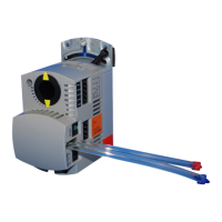
EPIA6.... Power interface
EPIMSA6
Master/Slave interface for the control of up to
4 fan coils (< 3 A)
M........... Fan coil motor
VHC ...... Solenoid valve
VC......... Cooling solenoid valve
VH......... Heating solenoid valve
TSA....... Automatic safety thermostat
TSM ...... Safety thermal fuse
SC......... Cabling box
.......... Ground
..... Electrical connections to be made by the
installer
..... Part of diagram valid only for the centralised
remote Cooling/Heating selector switch
(CRHC)
NOTE
If you wait more than 5 seconds before
turning the knob again, the autodiagnosis
mode will be automatically exited.
Position Output Terminals
Valve N-V
Minimum speed N-V1
Medium speed N-V2
Maximum speed N-V3
Electric heater
or second valve
N-RE
NOTE
If the operating mode selector switch is not
moved for more than one minute, the
autodiagnosis mode is automatically
exited.
1B_I+OM_4PW17551-1B.book Page 13 Wednesday, October 5, 2005 9:18 AM
 Loading...