Do you have a question about the Daikin EHBX08EA6V and is the answer not in the manual?
Provides an overview of the installation manual's content and purpose.
Details on accessing the latest technical data for installation and servicing.
Safety precautions for choosing and preparing the unit's installation location.
Safety precautions for refrigerant and water piping installation.
Safety warnings for electrical connections and handling.
Lists and describes accessories found inside the indoor unit packaging.
Covers requirements and guidelines for selecting and preparing the installation location.
Specifies ambient temperatures and spacing for indoor unit installation.
Step-by-step guide for accessing internal components and reassembling the unit.
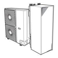
Instructions for securely attaching the indoor unit to the wall bracket.
Procedure for connecting the drain pan to an appropriate drainage system.
Details requirements for refrigerant piping materials, diameter, and thickness.
Guidelines for insulating refrigerant pipes to prevent condensation and heat loss.
Requirements for water piping, including oxygen diffusion tightness.
Ensuring minimum water volume and flow rate for proper system operation.
Procedure for connecting liquid and gas refrigerant pipes to the indoor unit.
Instructions for installing shut-off and bypass valves for water piping.
Ensures adherence to electrical standards and wiring guidelines.
Details connections for power supply, valves, sensors, and other components.
Wiring for heat convectors, sensors, DHW tanks, and network adapters.
Requirements for LAN adapter application, app control, and Smart Grid.
Procedure for connecting the main power supply to the indoor unit.
Information on connecting preferential kWh rate power supply and safety thermostat.
Step-by-step guide for connecting the backup heater power supply.
Procedure for connecting shut-off valves and electricity meters.
Wiring for DHW pump and alarm output signal.
Wiring for ON/OFF output and changeover to external heat source.
Wiring for digital inputs and safety thermostat.
Details for connecting to a Smart Grid using low or high voltage contacts.
Steps for installing the Smart Grid relay kit components and wiring.
Introduction to system configuration and its impact on unit operation.
Methods for accessing and changing installer settings via the user interface.
Wizard steps for setting language, time, and date.
Wizard step to configure backup heater and domestic hot water settings.
Settings for backup heater, emergency operation, and zone configuration.
Setting backup heater voltage, configuration, and capacity steps.
Setting emitter type, control mode, and setpoint for the main zone.
Defining setpoint modes and schedule adjustments for the main zone.
Settings for emitter type and control for the additional water zone.
Adjusting weather-dependent curves using slope and offset.
Defining weather-dependent curves using two setpoints or slope/offset.
Configuring hot water heat up modes and comfort/eco setpoints.
Explains the function and advantage of weather-dependent operation.
Guide on configuring weather-dependent curves for zones and tank.
Specifying setpoint modes for zones and tank to enable weather-dependent operation.
Selecting the type of weather-dependent curve for zones and tank.
Configuring the thermostat type for the main zone, including frost protection.
Configuring the thermostat type for the additional zone.
Space for installer to record contact information for support.
Provides a hierarchical view of all available installer settings.
A comprehensive checklist for verifying installation and unit readiness.
Items to check after installation but before powering on the unit.
Tasks to perform during the commissioning process to ensure proper operation.
Procedure to verify the minimum flow rate and adjust bypass valve.
Steps to purge air from the system and heat emitters.
Running tests to verify operation and individual components.
Procedure for the underfloor heating screed dryout function.
Important notice regarding screed dryout and room frost protection settings.
Steps for explaining operation, maintenance, and energy saving tips to the user.
Schematic showing refrigerant and water piping connections for the indoor unit.
Diagram illustrating internal wiring and terminal connections of the indoor unit.
Explanation of abbreviations and symbols used in the wiring diagrams.
Glossary of terms and their translations used in wiring diagrams.
Overall electrical connection diagram for standard and optional parts.
Table showing maximum allowed refrigerant charge based on room size and height.
Table detailing minimum floor area needed per refrigerant charge and height.
Table specifying minimum venting opening areas for natural ventilation.
Clarifies how to use intermediate values for height and refrigerant charge in tables.
| Energy Efficiency Class (Heating) | A++ |
|---|---|
| Refrigerant | R-32 |
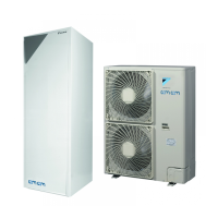
| Dimensions (Indoor Unit) | 890 x 480 x 344 mm |
| Dimensions (Outdoor Unit) | 870 x 765 x 345 mm |
| Type | Air to Water Heat Pump |
| Noise Level (Indoor) | 29 dB |
| Power Supply | 230V / 1 Phase / 50Hz |