19 | Configuration
Installer and user reference guide
80
EKVDX32~100A2VEB
VRV system air conditioner
4P664010-1 – 2021.08
19.4 Field settings
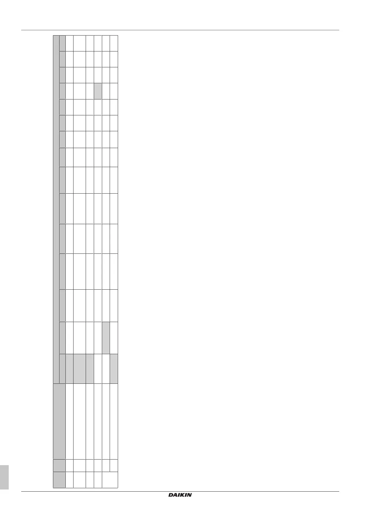
EKVDX field settings (user interface: indoor unit 0)
Mode SW SW description SW position
(a)
01 02 03 04 05 06 07 08 09 10 11 12 13 14 15
10 (20)
(b)
13 Discharge temperature correction factor (°C) 0 0.5 1 1.5 2 2.5 3 3.5 4 4.5 5 5.5 6 6.5 7
12(22)
(c)
1 External input switching (T1 T2 ) Forced stop
(default)
External Input
(ON:OFF operation)
Protective device
input
Forced stop B (multi-
tenant setting)
— — — — — — — — — — —
14 (24)
(d)
10 Cooling blowout temperature setpoint 13°C 15°C 16°C 17°C 18°C 19°C 20°C 21°C 22°C 23°C 24°C 25°C 26°C 28°C 30°C
14 (24)
(d)
11 Heating blowout temperature setpoint 24°C 26°C 27°C 28°C 29°C 30°C 31°C 32°C 33°C 35°C 37°C 39°C 41°C 43°C 45°C
15 (25) 13 R32 safety system
(e)
OFF ON OFF for 24 hours — — — — — — — — — — — —
15 External contact output settings
(f)
Disable Enable — — — — — — — — — — — — —
(a)
Factory settings are marked with a grey background.
(b)
This field setting cannot be modified via the remote controller menu.
(c)
In case of R32 refrigerant, terminal connections T1 T2 are for fire alarm input ONLY.
(d)
The VAM field setting 18(28)-13/-14 (see table below) MUST be identical to the EKVDX field setting. Set the EKVDX first (EKVDX=primary, VAM=secondary)
(e)
In case R410A is used, set to 15(25)-13-1.
(f)
15(25)-15-2 is required when R32 refrigerant is used.



 To Next Page