16 | Technical data
Installer reference guide
249
ERGA04~08EAV3(A) + EHVH04+08SU18+23EA6V
Daikin Altherma 3 R F
4P629090-1 – 2020.08
16 Technical data
A subset of the latest technical data is available on the regional Daikin website
(publicly accessible). The full set of latest technical data is available on the Daikin
Business Portal (authentication required).
In this chapter
16.1 Piping diagram: Outdoor unit................................................................................................................................................. 249
16.2 Piping diagram: Indoor unit.................................................................................................................................................... 251
16.3 Wiring diagram: Outdoor unit ................................................................................................................................................ 252
16.4 Wiring diagram: Indoor unit ................................................................................................................................................... 254
16.5 Table 1 – Maximum refrigerant charge allowed in a room: indoor unit............................................................................... 260
16.6 Table 2 – Minimum floor area: indoor unit............................................................................................................................ 261
16.7 Table 3 – Minimum venting opening area for natural ventilation: indoor unit .................................................................... 261
16.8 ESP curve: Indoor unit ............................................................................................................................................................ 263
16.9 Technical specifications: Domestic hot water tank ............................................................................................................... 263
16.9.1 Test results in accordance with EN12897 (2016).................................................................................................. 263
16.9.2 Warning label ......................................................................................................................................................... 264
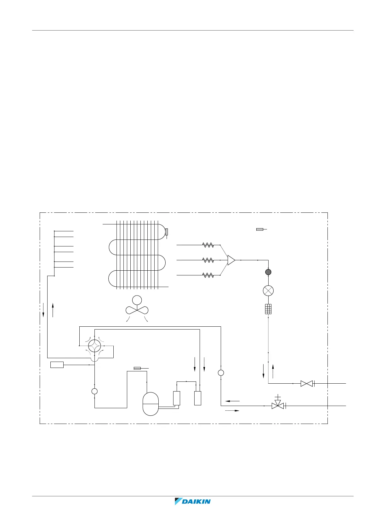
16.1 Piping diagram: Outdoor unit
R2T
7.0 CuT
7.0 CuT
7.0 CuT
7.0 CuT
7.0 CuT
7.0 CuT
12.7 CuT
12.7 CuT
12.7 CuT
6.4 CuT
6.4 CuT
6.4 CuT
6.4 CuT
4.0 CuT
4.0 CuT
9.5 CuT
15.9 CuT
3D110394
9.5 CuT
12.7 CuT
15.9 CuT
6.4 CuT
S1PH
Y1E
R1T
R3T
M1C
Y1S
4.0 CuT
M1F
b
ac
d
e
f
g
h
ij
k
k
g
g
a Field piping (liquid: Ø6.4mm
flare connection)
M1C Compressor
b Field piping (gas: Ø15.9mm
flare connection)
M1F Fan
c Stop valve (liquid) R1T Thermistor (outdoor air)
d Stop valve with service port
(gas)
R2T Thermistor (heat exchanger)