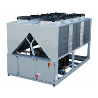
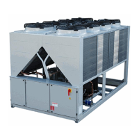
ESIE11-05 Wiring Diagram
General Outline 37
Switch box layout
Notes
1. This wiring diagram only applies to the outdoor unit
2.
: field wiring : indication of parts outside switch box
3.
: terminal strip : connector : terminal : protective earth (screw)
4. When using the option adapter, refer to the installation manual
5. Refer to the installation manual, for connection wiring to hydrobox-outdoor transmission F1-F2, transmission F1-F2 for option
DTA104A62 and on how to use BS1~BS5 and DS1, DS2 switch.
6. Do not operate the unit by short-circuiting protection device S1PH
7. BLK = Black, RED = Red, BLU = Blue, WHT = White, PNK = Pink, YLW = Yellow, BRN = Brown, GRY = Grey, GRN = Green, ORG =
Orange

 Loading...

