English 19
Wiring Method
(3) Remove the control box lid (Refer to ‘‘5. INDOOR UNIT INSTALLATION’’.)
(4) Add wiring between the remote controller 2 (slave) and the terminal (P1, P2) of the terminal block
(X1M) for the remote controller in the control box. (There is no polarity.) (Refer to Fig. 28 and Table
4)
1. All transmission wiring except for the remote controller wires is polarized and must match the terminal
symbol.
2. In cases of group control, perform the remote controller wiring to the master unit when connecting to the
simultaneous operation system. (Wiring to the slave unit is unnecessary.)
3. In case of group control and simultaneous operation system remote controller, choose the remote con-
troller that suits the indoor unit which has the most functions (as attached swing flap).
4. For simultaneous operation system, connect the remote controller cord to the master unit.
10. FIELD SETTING
〈
Complete all the “1. Items to be checked after completion of work” on page 4.
〉
• Make sure that the installation and wiring work for the indoor and outdoor units is all completed.
• Make sure that the following items are all closed: the control box lid of the indoor unit and the outer board
and piping cover of the outdoor unit.
<Field setting must be made from the remote controller in accordance with the installation conditions.>
• Setting can be made by changing the “Mode No.”, “FIRST CODE NO.”, and “SECOND CODE NO.”.
• For setting procedures and instructions, see the manual provided with the remote controller.
• The “Mode No.” is normally set collectively for a group. In order to set each indoor unit individually and per-
form checks after the settings, specify the Mode No. in parenthesis.
• Do not perform settings that are not listed in the table.
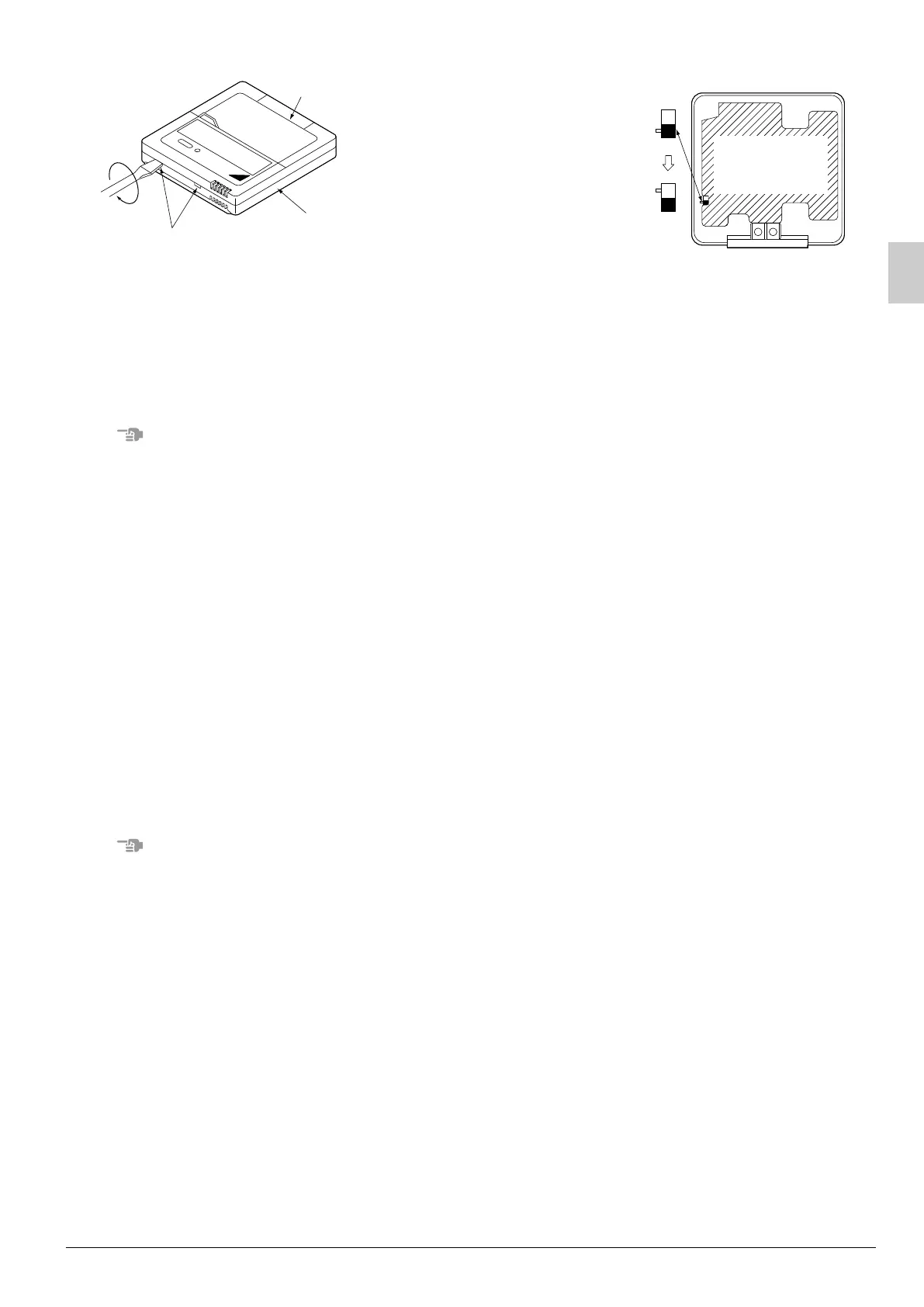
Upper case of
remote controller
Lower case of
remote controller
Insert the screwdriver
here and gently work
off the upper part of
remote controller.
Fig. 29
S
M
S
S
M
Remote
controller printed
circuit board
(Factory setting)
(Only one remote
controller needs
to be changed if
factory settings
have remained
untouched.)
Fig. 30
3P184443-9J_FM6.book Page 19 Wednesday, December 14, 2011 10:29 AM

 Loading...