• Split Sky Air • Indoor Units
9
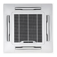
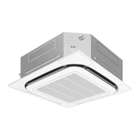
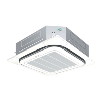
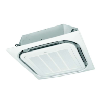
• Indoor Units • R-410A • FCQ-C8VEB
5 Dimensional drawing & centre of gravity
5 - 3 Dimensional drawing with accessories
Nr Name Description
1 Indoor unit
2 Decoration panel
3 Suction chamber
4 Connecting chamber (Right)
5 Connecting chamber (Left)
NOTES
1 When installing this kit, inspection hatch is necessary.
(It is necessary when servicing.) Either one of
inspection hatches must be installed.
2 Field construction.
3 The corner air outlet of this part must be shut.
4 In case of mounting a duct fan, make sure to use a wiring adapter for
electrical appendices and link with the indoor unit fan.
1 The intake air flow rate is recommended to be 20%
or less of the H speed air flow rate.
If the intake air flow rate is too large, the operating
sound may rise or detection of the indoor unit suction temperature may be affected.
2 It indicates the distance between the T-tube inlet and the
indoor unit inlet when the T-tube is connected.
Ventilation resistance in chamber (note 6)
Service acces panel:
450 x 450 mm or more
(Refer to note 1)
Service acces panel:
450 x 450 mm or more
(Refer to note 1)
Installation service access panel
note 3
note 3
Pipe connection side
Drain connection side
View A
455 (Ceiling opening panel)
Connecting chamber mounting space
T-tube
Field supply
Air flow rate (m
3
/min)
Static pressure of chamber (Pa)
Inlet
(*) In case a discharge opening is closed with the ‘sealing member’ option, the distance of 1500 mm can be reduced to 500 mm on the closed side
Nr Name Description
1 Indoor unit
2 Decoration panel
3 Suction chamber
4 Connecting chamber (Right)
5 Connecting chamber (Left)
NOTES
1 When installing this kit, inspection hatch is necessary.
(It is necessary when servicing.) Either one of
inspection hatches must be installed.
2 Field construction.
3 The corner air outlet of this part must be shut.
4 In case of mounting a duct fan, make sure to use a wiring adapter for
electrical appendices and link with the indoor unit fan.
1 The intake air flow rate is recommended to be 20%
or less of the H speed air flow rate.
If the intake air flow rate is too large, the operating
sound may rise or detection of the indoor unit suction temperature may be affected.
2 It indicates the distance between the T-tube inlet and the
indoor unit inlet when the T-tube is connected.
Ventilation resistance in chamber (note 6)
Service acces panel:
450 x 450 mm or more
(Refer to note 1)
Service acces panel:
450 x 450 mm or more
(Refer to note 1)
Installation service access panel
note 3
note 3
Pipe connection side
Drain connection side
View A
455 (Ceiling opening panel)
Connecting chamber mounting space
T-tube
Field supply
Air flow rate (m
3
/min)
Static pressure of chamber (Pa)
Inlet
306
(*) In case a discharge opening is closed with the ‘sealing member’ option, the distance of 1500 mm can be reduced to 500 mm on the closed side.
 Loading...