• Split Sky Air • Indoor Units
7
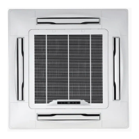
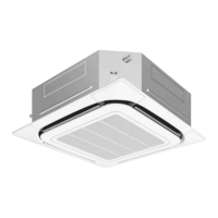
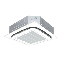
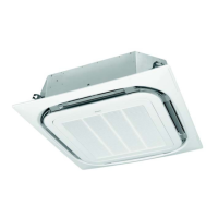
• Indoor Units • R-410A • FCQ-C8VEB
5 Dimensional drawing & centre of gravity
5 - 1 Dimensional drawing for standard panel
Nr Name Description
1 Liquid pipe connection ø A flare connection
2 Gas pipe connection ø B flare connection
3 Drain pipe connection VP25 (O.D. ø 32 /I.D. ø 25)
4 Power supply entry hole
5 Transmission wiring entry hole
6 Air discharge opening
7 Air suction grille
8 Corner decoration cover
9 Drain hose O.D. ø 32 /I.D. ø 26
10 Knock out hole
Piping side
Drain side
SEE NOTE 3
300 or less
860-910 (Ceiling opening)
710 (Suspension position
950
420
420
780 (Suspension position
860-910 (Ceiling opening)
SEE NOTE 4
175
850
Adjustable (0-675)
125
55
840
340
280
330
165
214
55
55 55
35
SEE NOTE
4
SEE NOTE
4
840
130
35
1500 or more
(installation space)
1500 or more
2000 or more
4000 or more
EXTERNAL
SURFACE
LIGHT
VENTILATOR OTHER UNIT
1500mm
or more (*)
1500mm
or more (*)
1500mm
or more (*)
200mm
or more
1500mm
or more (*)
200mm
or more
(*) In case a discharge opening is closed with the ‘sealing member’ option,
the distance of 1500mm can be reduced to 500mm on the closed side.
Hanging bolt
4 x M8~M10
MODEL A B
FCQ35 6.35 9.52
FCQ50-60 6.35 12.7
FCQ71 9.52 15.9
213
139
7
5
VIEW B
VIEW A
SEE NOTE
6
950
50 204
40
10
NOTES
1 Location of the nameplates
- Unit body: on the control box cover.
-
Decoration panel: on the panel frame at the motor side under the corner cover
2 When installing an optional accessory, refer to the installation drawings.
- For the fresh air intake kit an inspection port is necessary
3
In case of using an infrared remote control, this position will be a signal
receiver. Refer to the drawing of the infrared remote control for more detail.
4 Make sure the spacing between the ceiling and the cassette is no more
than 35mm. MAX ceiling opening: 910mm.
5 When the conditions exceed 30°C and RH 80% in the ceiling or fresh air
is inducted into the ceiling, an additional insulation is required
(polyethylene foam, thickness 10mm or more).
6 Please respect the distances as shown on the figure
FCQ(H)100-140C8
3TW28914-1C
Piping side
Drain side
see note 3
see note 4
300 or less
(Ceiling opening)
(Suspension position)
(Suspension position)
(Ceiling opening)
Please respect the distances as shown on figure below
Other unit
Ventilator
External
surface
light
1500 or more
2000 or more
4000 or more
1500 mm
or more (*)
1500 mm
or more (*)
1500 mm
or more (*)
1500 mm
or more (*)
200 mm
or more
200 mm
or more
(*) In case a discharge opening is closed with
the “sealing member” option, the distance of
1500 mm can be reduced to 500 mm on the
closed side.
see note 4
see note 4
Hanging bolt
adjustable
1500 or more
(Suspension position)
View A
View B
Item Name Remark
1 Liquid pipe connection ø9.52 (Flare connection)
2 Gas pipe connection ø15.90 (Flare connection)
3 Drain pipe connection VP25 (ODø32, IDø25)
4 Power supply entry hole
5
Transmission wiring entry hole
6 Air discharge opening
7 Air suction grille
8 Corner decoration cover
9 Drain hose ODø32, IDø25
10 Knock out hole
NOTE
1 Location of the nameplates - Unit body: on the control box - Decoration panel: on the panel frame at the motor side under the corner cover
2 When installing an optional accessory, refer to the installation drawings
For the fresh air intake kit an inspection port is necessary
3 In case of using a wireles remote control, this position will be a signal receiver. Refer to the drawing of the wireless remote control for more detail.
4 Make sure the spacing between the ceiling and the cassette is no more than 35mm. Max cailing opening: 910mm.
5 When the conditions exceed 30°C and RH 80% in the ceiling or fresh air is inducted into the ceiling, an additionalinsulation is required (polyethylene foam,
thickness 10mm or more).
 Loading...